
Every relay engineer has lived the moment: a differential element asserts, the breaker opens, the load goes dark — and then the real question arrives. Was it a genuine internal fault, or did the protection system just lie to you? The answer shapes everything that happens next: whether you re-energize in minutes or begin a weeks-long investigation of winding insulation, whether the root cause is a five-cent wiring error or a catastrophic turn-to-turn short.
Differential protection — ANSI device 87 — remains one of the most trusted and most misunderstood schemes in power system protection. Its operating principle is elegant. Its failure modes are not. This article walks through the physics that makes it work, the practical realities that make it misbehave, and a systematic diagnostic path for field engineers facing a trip they need to explain.
The Operating Principle: Kirchhoff Made Practical
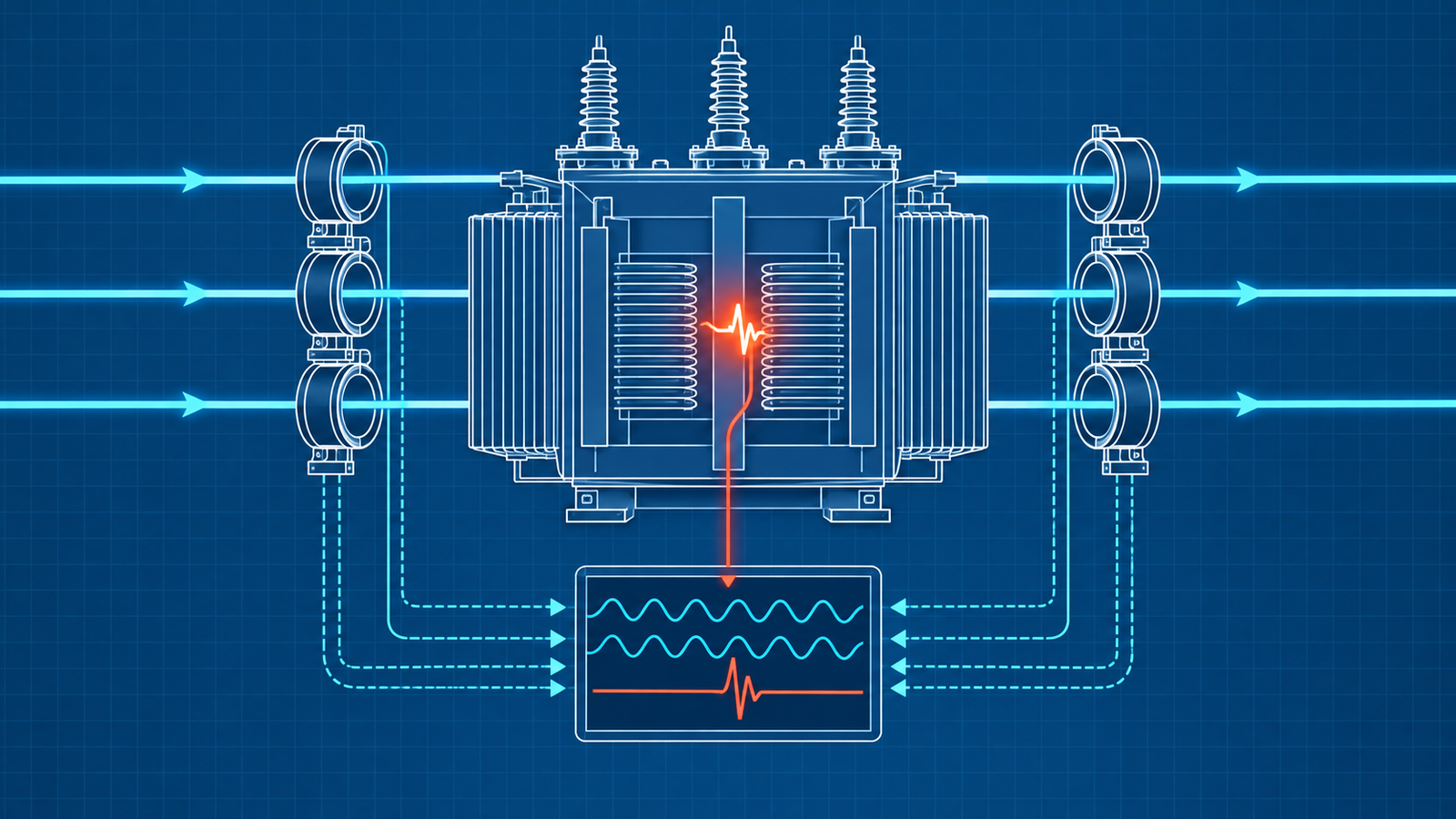
Differential protection rests on Kirchhoff’s current law applied to a zone. Under normal load or during an external fault, the sum of currents entering and leaving the protected equipment — a transformer, generator, motor, bus, or line — should be zero. Current transformers on each terminal of the protected zone produce secondary currents that are compared by the relay. If the currents balance, there is no internal fault, and the relay restrains. If they do not balance, the difference (the “operate” quantity) indicates that current is being consumed or generated within the zone, meaning a fault exists inside the protected equipment.
In its simplest form, a differential relay measures the vector sum of all CT secondary currents. When no fault exists inside the zone, the secondary currents cancel. The relay sees zero differential current. When an internal fault diverts current away from the normal path — say, a winding-to-ground fault in a transformer or a phase-to-phase short within a generator stator — the CT secondary currents no longer cancel. The relay sees a net operate current that exceeds its pickup threshold, and it issues a trip command.
This would be straightforward if current transformers were perfect devices and if protected equipment never produced transient imbalances. They are not, and it does.
Percentage Restraint: Why Simple Differential Isn’t Enough
A plain differential relay with a fixed pickup threshold trips whenever the operate current exceeds, say, 0.3 A secondary. The problem is that even healthy CTs cannot perfectly replicate the primary current at all magnitudes. Small differences in CT ratio accuracy, magnetization characteristics, lead resistance, and burden produce a residual mismatch that grows as load current increases. At high through-fault currents — which can reach tens of thousands of amperes on the primary side — even a 1% mismatch between CTs yields a differential current that easily exceeds a fixed threshold.
The percentage differential relay solves this by plotting its operating characteristic on a plane of operate current (Iop) versus restraint current (Irt). The operate current is the magnitude of the vector sum of all winding currents:
Iop = |IW1 + IW2 + ⋯ + IWn|
The restraint current is typically a scalar sum or average magnitude that represents the through current:
Irt = (|IW1| + |IW2| + ⋯ + |IWn|) / 2
The relay trips only when the operate current exceeds a defined percentage (the slope) of the restraint current and also exceeds a minimum pickup threshold. At low currents, the minimum pickup dominates. At high currents, the slope dominates, demanding proportionally more differential current before tripping. This dual-slope or even triple-slope characteristic is what allows the relay to remain secure during external faults with CT saturation while still detecting internal faults sensitively at lower current levels.
Understanding the percentage differential characteristic is essential to diagnosis because it tells you exactly where on the operating plane the relay was sitting when it tripped — and where it should have been sitting if the system were healthy.
Compensations: Phase Shift, Zero Sequence, and Tap Ratios
Transformer differential protection adds another layer of complexity because the protected equipment itself changes the current. A transformer’s primary and secondary currents differ by the turns ratio, and the winding configuration — delta, wye, zigzag — introduces phase shifts. A Dyn11 transformer, for example, shifts secondary currents 30° relative to primary currents. A Yd1 shifts them 30° the other way.
In electromechanical and early electronic relay eras, these compensations were performed by connecting CTs in delta or wye configurations opposite to the transformer winding they monitored, and by selecting CT ratios that accounted for the transformer turns ratio. A CT in delta removes zero-sequence current and introduces a √3 factor and a 30° shift — exactly compensating a wye-connected transformer winding.
Modern numerical relays perform these compensations mathematically. The engineer programs the transformer’s vector group, the nominal tap position, and the CT ratios on each winding. The relay’s firmware applies the corresponding rotation matrix and scaling factors internally. This is more flexible and eliminates the need for interposing CTs, but it also means that a single incorrect setting — entering Dyn11 when the transformer is Dyn1, or swapping the CT ratio numerator and denominator — produces exactly the kind of standing differential current that mimics an internal fault.
Zero-sequence removal is another critical compensation. During an external ground fault on a grounded-wye winding, zero-sequence current flows through the transformer neutral and through the CTs on the grounded side, but it does not pass through the transformer to the other winding. Without removing this zero-sequence component from the differential calculation, the relay would see it as operate current and trip falsely. Numerical relays apply zero-sequence filtering automatically when configured correctly, but if the winding configuration is entered wrong, the filter is either applied where it shouldn’t be or omitted where it must be.
Real Fault Trips: The Protection Doing Its Job
Before discussing spurious operations, it is worth understanding what a correct differential trip looks like, because the diagnostic path must first distinguish between correct and incorrect operations.
Turn-to-turn faults are among the most insidious. A few shorted turns in a transformer winding draw circulating current locally, reducing the effective turns ratio slightly. The differential current may be modest — barely above the operate threshold — and the fault current may not be large enough to cause dramatic thermal or mechanical damage immediately. Dissolved gas analysis typically reveals acetylene and hydrogen long before the differential relay sees enough operate current to trip. When a turn-to-turn fault finally produces a differential trip, the winding is often already significantly degraded.
Phase-to-ground and phase-to-phase faults within the zone produce unambiguous differential current. The operate current rises sharply, the restraint current rises as well (because the fault is fed from both sides), but the operate-to-restraint ratio lands well above the slope characteristic. These trips are fast — typically one to two cycles for numerical relays — and the oscillography shows a sudden, clean departure from the pre-fault balanced state.
Bushing failures, lead faults, and tap-changer faults also fall within the differential zone. A bushing flashover between the CTs on the high-voltage side and the transformer tank is inside the zone and produces correct operation. But a lead fault between the CT and the breaker may or may not be in the zone depending on exact CT placement — a subtlety that matters during post-trip investigation.
Spurious Trips: When the Protection Lies
Incorrect differential operations fall into a handful of well-understood categories. Knowing them before you begin diagnosis lets you work from pattern recognition rather than groping in the dark.
Magnetizing Inrush
When a transformer is energized, its core may be driven into magnetic saturation on one half of the voltage cycle, producing a large, asymmetric, peaked magnetizing current on the energized winding. No corresponding current appears on the other winding because the transformer is unloaded or lightly loaded at the instant of energization. The differential relay sees the full inrush current as operate quantity.
Inrush current is rich in even-order harmonics, particularly the second harmonic. Classical relays used second-harmonic restraint or blocking: if the ratio of second-harmonic content to fundamental content in the operate current exceeded a threshold (typically 15–20%), the relay would restrain or block tripping. This worked reliably for decades. It is becoming less reliable.
Modern power transformers built with high-grade cold-rolled grain-oriented (CRGO) steel have lower core losses and sharper saturation curves. The result is that their inrush current waveforms contain less second-harmonic content — sometimes below 10% of the fundamental. A relay with a 15% second-harmonic restraint threshold sees this inrush as an internal fault, because the harmonic content is too low to trigger the blocking logic. This is not a theoretical concern; it is a documented cause of misoperation in modern substations with modern transformers and modern relays.Source
Sympathetic inrush compounds the problem. When one transformer in a parallel bank is energized, the voltage distortion caused by its inrush can partially saturate the core of the already-energized adjacent transformer, producing a sympathetic magnetizing current that adds to the differential current seen by the second transformer’s relay. The sympathetic inrush builds gradually, which means the second-harmonic content may ramp slowly enough to defeat time-domain harmonic detection algorithms.
CT Saturation During External Faults
During a heavy external fault — a bolted three-phase short on the secondary bushings, for instance — the through-fault current may reach the CT’s saturation limit, particularly if the fault current contains a significant DC offset (high system X/R ratio). When one set of CTs saturates and the other does not, the relay sees a transient differential current that mimics an internal fault.
The percentage differential characteristic provides some security against this because the restraint current is also high during an external fault. But if the CT saturation is severe and asymmetric — one CT delivering a badly distorted secondary current while the other faithfully reproduces the waveform — the operate current can breach the slope characteristic. Modern relays address this with directional comparison logic, external fault detection algorithms, and adaptive restraint that increases the slope when CT saturation signatures are detected. Older relays, or modern relays with these features disabled, remain vulnerable.Source
CT Wiring and Polarity Errors
This is the most common cause of differential trips during commissioning and the most common cause of nuisance trips discovered after years of apparently successful operation. A CT with reversed polarity effectively subtracts its current from the balance equation instead of adding it, doubling the apparent differential current at load. A stray ground on a CT secondary circuit creates a parallel path that diverts current away from the relay, producing a standing differential error that varies with load. Dual grounding of a CT secondary — ground at the CT junction box and again at the relay panel — is a classic error that may not manifest at low loads but produces significant differential current under heavy load or during fault conditions because the ground loop impedance becomes significant relative to the burden.Source
The insidious aspect of CT wiring errors is that they can remain hidden for months or years. If the error produces a differential current that remains below the minimum pickup threshold at normal load levels, the relay never trips — until a heavy load day, a motor start, or a through-fault pushes the current high enough to cross the operate characteristic. The relay then trips on what appears to be a legitimate differential operation, and the investigation focuses on the transformer or generator instead of on the secondary wiring.
Overexcitation
When a transformer is subjected to a voltage higher than its rated volts-per-hertz capability — during load rejection at a generating station, for example, when a unit-connected generator suddenly loses its reactive load and the voltage rises — the core saturates symmetrically on both half-cycles. The resulting magnetizing current is rich in odd harmonics, particularly the fifth. Differential relays equipped with fifth-harmonic restraint will ride through this condition, but relays without this feature, or with the feature set to an inappropriate threshold, may trip.Source
Incorrect Relay Settings
The relay is a computing device that applies a mathematical model to measured currents. If the model does not match the physical system, the computed differential current will be wrong even if the measured currents are correct. Incorrect CT ratios, wrong vector group compensation, wrong tap position setting, disabled zero-sequence removal on a grounded winding, or an operate pickup set too sensitively — any of these can produce an incorrect trip. A generator differential relay with a pickup of 0.07 per unit, for example, leaves almost no margin for CT mismatch, load imbalance, or transient effects; industry practice recommends a minimum of 0.20–0.30 per unit for generator applications.Source
Tap Changer Operation
On-load tap changers alter the effective turns ratio of the transformer. The relay’s compensation is typically set for the mid-tap or nominal position. As the tap moves to extreme positions, the ratio mismatch between the actual transformer ratio and the relay’s assumed ratio increases, producing a standing differential current. If the relay’s slope setting doesn’t provide enough margin for the full tap range, an extreme tap position combined with high load can push the operating point above the characteristic.
The Diagnostic Path
When a differential relay trips, the clock starts. Operators want to know if they can re-energize. Management wants a cause. The following is a structured sequence that moves from the most informative and least invasive steps toward the most time-consuming ones.
Step 1: Retrieve the Event Record
Before touching anything in the field, pull the relay’s event report. Modern numerical relays store oscillography (typically 16–64 samples per cycle), phasor snapshots, sequence-of-events logs, and digital element status for every trip event. This single data set contains more diagnostic information than any other source, and it will be overwritten if the relay trips again. Download it, archive it, and time-stamp it.Source
From the event record, extract:
Which element operated. Was it the restrained differential (87R), the unrestrained or instantaneous differential (87U), or the restricted earth fault (87N/REF)? An 87U trip indicates extremely high differential current — consistent with a heavy internal fault or a gross CT error. An 87R trip at modest current levels suggests a subtler mismatch.
The operate and restraint currents at the instant of trip. Plot these on the relay’s percentage differential characteristic. Where did the operating point land? Was it deep in the operate region (clear fault) or barely above the slope line (marginal — possibly CT error or setting issue)?
The pre-fault currents. Was there a standing differential current before the trip event? A healthy system shows near-zero differential current at steady state. A standing value — even below pickup — indicates a persistent error: CT mismatch, incorrect compensation, or wiring problem.
The harmonic content. If the relay logs second and fifth harmonic magnitudes in the operate current, check them. High second harmonic suggests inrush; high fifth harmonic suggests overexcitation. Low harmonic content during what appears to be inrush may indicate the modern-CRGO problem described earlier.
The current waveforms. Raw oscillography reveals what the phasor quantities cannot. CT saturation produces characteristic flat-topped or clipped waveforms. Inrush produces asymmetric peaked waveforms with a quiet half-cycle. A genuine internal fault typically shows a sudden increase in current magnitude with preserved sinusoidal shape (at least initially, before CT saturation sets in).Source
Step 2: Correlate with System Events
Check the SCADA historian and the sequence-of-events recorder for what was happening on the system at the time of the trip. Was the transformer being energized? Was a parallel transformer being switched? Was there a fault on an adjacent feeder that could produce sympathetic inrush or through-fault CT saturation? Was the tap changer at an extreme position? Was the generator absorbing or exporting a large amount of reactive power?
If the trip occurred during energization and the oscillography shows inrush waveform characteristics, you are likely dealing with an inrush-related misoperation. If the trip occurred during a through-fault and the waveforms show CT saturation signatures, that is your leading hypothesis. If the trip occurred under steady-state conditions with no system disturbance, the cause is more likely a wiring error, a setting error, or a genuine developing fault.
Step 3: Inspect the Relay Settings
Pull the active settings file from the relay and verify every parameter against the as-built drawings and the protection study.
Check the CT ratios entered for each winding. A surprisingly common error is entering the CT ratio as 2000:1 when the CTs are connected at a 1000:1 tap, or entering the nominal ratio when the relay expects the connected ratio.
Verify the vector group compensation. For a Dyn11 transformer, confirm that the relay is applying a +30° rotation to the correct winding and that the phase sequence matches the relay’s convention (some manufacturers define Dyn11 with respect to the primary, others with respect to the secondary).
Check the zero-sequence removal settings. A grounded-wye winding should have zero-sequence removal enabled. A delta winding naturally blocks zero-sequence current and typically does not need the setting, but some relay models require it to be explicitly configured.
Confirm the minimum pickup, slope settings, and harmonic restraint thresholds. Compare these against the original relay setting study and against the manufacturer’s recommended ranges.
Step 4: Analyze the Phasor Relationships
Using the event record phasor data or by performing a load study with the relay in metering mode (if the equipment can be re-energized under controlled conditions), examine the phase relationships between winding currents.
Under balanced load, the currents on the primary and secondary (after compensation) should be approximately equal in magnitude and 180° apart. Any deviation indicates a compensation error, a CT polarity reversal, or an actual current imbalance within the equipment.
Check the phase sequence on each winding. Phases A, B, and C should be separated by 120° and should rotate in the correct sequence. A swapped pair of CTs on one winding will disrupt this pattern on two phases simultaneously.
If the relay supports metering-mode differential current display, read the standing differential current under load with no trip enabled. This is the clearest indicator of whether the system is correctly balanced.
Step 5: Perform CT Circuit Testing
If the event record and setting review do not conclusively explain the trip, and the equipment is de-energized, perform a thorough CT circuit test.
Resistance test. Measure the DC resistance of each CT secondary circuit from the CT terminals to the relay terminals and back. Compare phases. A resistance significantly different from its mates suggests a loose connection, corroded terminal, or broken conductor.
Insulation test. Megger each CT secondary circuit to ground and to adjacent circuits. A low reading indicates insulation breakdown that could create a parallel ground path.
Polarity verification. Using a DC flick test or a CT analyzer, confirm the polarity marking on each CT. Then trace the wiring from the CT to the relay terminal to confirm that the polarity is maintained through every junction, marshalling box, and terminal strip.
Single-point ground verification. Confirm that each CT secondary circuit is grounded at exactly one point, typically at the relay panel. Lift the intentional ground and measure insulation resistance to ground to detect any stray grounds in the circuit.
CT excitation test. Apply voltage to the CT secondary and measure the excitation current. Plot the V-I curve and compare it to the manufacturer’s published curve. A CT with degraded core insulation (shorted turns) will draw excessive excitation current at low voltage and will produce a flattened excitation curve. This CT will not accurately reproduce the primary current at high magnitudes, producing differential error under load or fault conditions.
Step 6: Evaluate the Protected Equipment
If the CT circuits are proven correct and the relay settings are verified, the evidence points toward a genuine condition within the protected equipment. At this point, the investigation shifts from protection engineering to equipment diagnostics.
For transformers: review dissolved gas analysis trends, perform winding resistance measurements (comparing phases and looking for tap-changer contact degradation), perform a turns-ratio test on all taps, perform a sweep frequency response analysis (SFRA) if winding deformation is suspected, and inspect the Buchholz relay for gas accumulation.
For generators: perform a stator winding insulation resistance and polarization index test, an AC or DC hipot if warranted by the insulation test results, a surge comparison test to detect turn-to-turn insulation weakness, and a rotor ground detection test if the differential could be influenced by rotor ground currents coupling into the stator CTs.
For bus differential schemes: perform a physical inspection of all bus connections, insulators, and support structures within the differential zone.
Step 7: Staged Energization
If the equipment tests clear and the cause remains uncertain, consider a controlled re-energization with enhanced monitoring: relay in test mode with event recording active, digital fault recorder connected, and if possible, temporary CTs or current clamps on the primary conductors for comparison with the relay’s CT measurements.
Energize at reduced voltage if possible (for transformers, through a variable voltage source or by back-energization from the low-voltage side). Monitor the differential current as voltage is increased. A developing internal fault will produce differential current proportional to the applied voltage. An energization-related issue (inrush, CT saturation) will manifest only at full voltage.
A Note on Modern Relay Features and Their Limits
Numerical relays have dramatically improved the security and dependability of differential protection. Adaptive harmonic restraint, waveform recognition algorithms, CT saturation detection, high-security mode (HSM) for transformer energization, and even model-based approaches that track the transformer’s magnetic state in real time — these features address many of the classical failure modes described above.
But they are not infallible. Every feature has a setting, and every setting is a decision about the tradeoff between security (not tripping when you shouldn’t) and dependability (tripping when you should). A relay with high-security mode enabled will ride through most inrush events, but if an internal fault occurs simultaneously with energization — rare, but not impossible — the HSM may delay tripping. A relay with aggressive CT saturation detection may restrain during an external fault with CT saturation, but if the fault evolves from external to internal (a breaker failure, for instance), the restraint logic may slow the response.
The diagnostic path described here applies regardless of the relay’s vintage. Electromechanical, solid-state, or numerical — the physics are the same. The CTs are the same. The wiring is the same. The transformer is the same. What changes is the volume and quality of the diagnostic data available from the relay, and the number of software features that must be verified in the settings review.
Closing the Loop
A differential trip investigation is complete when you can explain the operate current. Not just note its magnitude, but account for its source: which physical current, flowing through which CT, with which error or which fault path, produced the differential quantity that the relay computed and acted upon. If you can reconstruct the relay’s calculation from independent measurements — CT test results, primary injection, or waveform analysis — and arrive at the same conclusion the relay did, you understand the trip. If the relay’s conclusion was correct, you have confirmed a genuine fault and can proceed with equipment repair. If the relay’s conclusion was incorrect, you have identified the error — in the CTs, the wiring, the settings, or the relay algorithm — and can correct it before re-energization.
The alternative — re-energizing without understanding the trip and hoping it doesn’t happen again — is how protection engineers create the conditions for the next unplanned outage.