
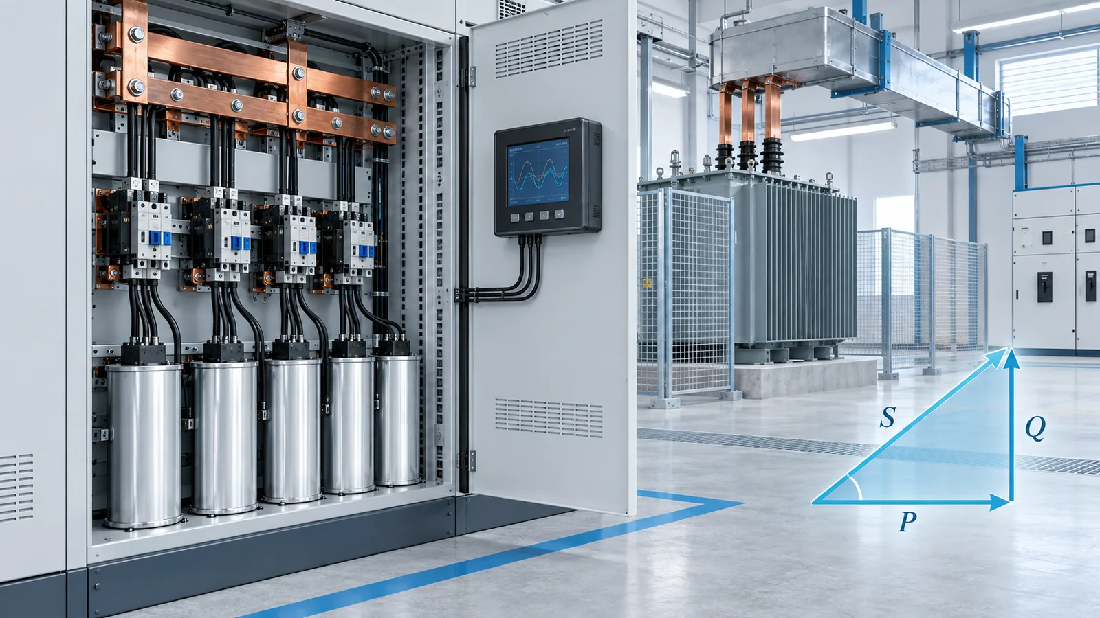
Raising a low power factor reduces the current and apparent power needed to deliver the same real power. That can reduce distribution losses and voltage drop, release transformer and cable capacity, and avoid tariff charges tied to kVA or reactive energy. It does not normally reduce the useful kWh consumed by the load itself, and correction equipment can create new problems if harmonics, switching duty, voltage rise, or light-load operation are ignored.
The engineering question is therefore not “How close can we get to unity?” It is “What correction target improves this system without overcompensation or resonance?”
Power factor in one equation
Power factor is the ratio of real power to apparent power:
PF = P (kW) / S (kVA)
For a balanced three-phase load:
I = P / (√3 × V × PF)
At fixed real power and voltage, current is inversely proportional to power factor. A 400 V load taking 500 kW at 0.70 power factor draws approximately:
I at PF 0.70 = 500,000 / (√3 × 400 × 0.70) ≈ 1,031 A
At 0.95 power factor, the same 500 kW requires about:
I at PF 0.95 = 500,000 / (√3 × 400 × 0.95) ≈ 760 A
That is roughly 26% less line current. The load still receives 500 kW; the upstream system simply carries less reactive current.
The U.S. Department of Energy’s motor-system guidance describes power factor as the ratio of real power to apparent power and explains that reactive current circulates through the source and distribution system without producing useful mechanical work. The same guide is a useful conceptual reference, but its examples do not replace a site-specific tariff or harmonic study.
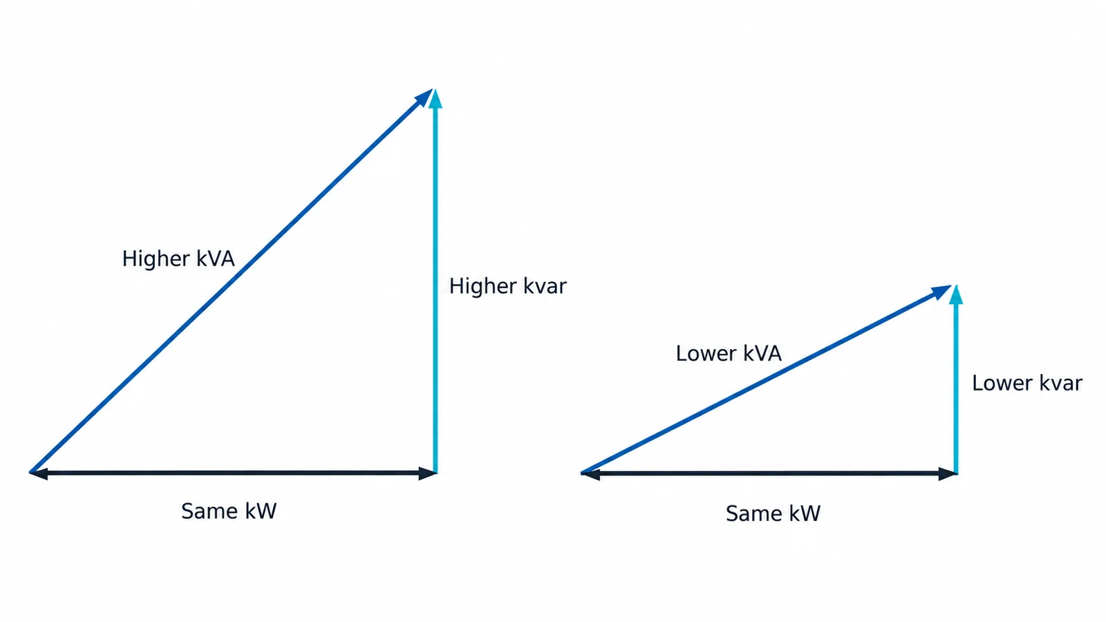
What engineers gain by improving power factor
Lower current for the same kW
Lower current reduces conductor and transformer loading. This can be valuable where a facility is close to a transformer kVA limit, feeder ampacity limit, or switchboard current rating. Correction may postpone an upgrade, but only if the limiting component is actually constrained by current or kVA rather than temperature, fault duty, protection, space, or another factor.
Lower I²R losses inside the facility
Resistive losses vary with the square of current. In the worked example, the current ratio is 760/1,031, so the current-dependent loss in the same conductor would be about:
(760 / 1,031)² ≈ 0.54
This does not mean the facility’s total energy use falls by 46%. It means that the loss in the particular current-carrying path is approximately 46% lower, assuming the same resistance and operating conditions. The overall savings depend on operating hours, load profile, conductor resistance, transformer losses, and where the correction is installed.
More usable electrical capacity
A transformer rated in kVA can supply more kW at a higher power factor, within its thermal, voltage, harmonic, and protection limits. For example, 1,000 kVA corresponds to 700 kW at 0.70 power factor but 950 kW at 0.95. This arithmetic identifies a possible capacity benefit; it is not permission to exceed any nameplate or engineered limit.
Better voltage performance in some systems
Reducing reactive current can reduce voltage drop across inductive source impedance. The magnitude and direction of the change depend on network impedance, correction location, load level, and control strategy. A weak system may benefit materially, while a stiff system may show little voltage change. Excess leading kvar at light load can instead raise voltage.
Lower utility charges where the tariff rewards it
Some tariffs bill maximum kVA, reactive energy, or a power-factor penalty; others do not. The financial case must use the actual utility tariff, meter interval, demand window, seasonal rules, and correction location. A high power factor on a handheld meter at one instant does not prove that monthly charges will change.
Displacement power factor is not the whole story
With nearly sinusoidal voltage and current, power factor is closely related to the phase angle between them. Nonlinear loads—such as rectifiers, variable-frequency drives, and switch-mode power supplies—distort current. Total power factor then includes both displacement and distortion effects.
A capacitor bank can improve displacement power factor while leaving harmonic current largely unchanged. It can also interact with system inductance and amplify a harmonic near a parallel-resonance frequency. IEEE 519-2022 establishes waveform-distortion goals at the point of common coupling; it is not a capacitor-sizing recipe, but it explains why harmonic performance must be evaluated at a defined system boundary.
How much reactive power is required?
For a target change from (PF_1) to (PF_2), the ideal fundamental-frequency correction is:
Qc = P × [tan(cos⁻¹(PF1)) − tan(cos⁻¹(PF2))]
For 500 kW improving from 0.70 to 0.95:
- tan(cos⁻¹(0.70)) ≈ 1.020
- tan(cos⁻¹(0.95)) ≈ 0.329
- Qc ≈ 500 × (1.020 − 0.329) = 346 kvar
The calculation suggests about 346 kvar at that operating point. A practical design still needs staged capacity, switching strategy, voltage tolerance, harmonic data, load variation, contactor or thyristor duty, protection, ventilation, discharge provisions, and coordination with embedded generation.
Correction methods and where each fits
| Method | Best fit | Main limitation |
|---|---|---|
| Individual correction | Large motor or steady inductive load | Can overcorrect when the load is disconnected or lightly loaded if control is wrong |
| Group correction | Several loads that operate together | Less precise when group diversity is high |
| Automatic central bank | Facility demand that changes in steps | Needs a suitable controller, switching design, measurements, and harmonic assessment |
| Detuned capacitor bank | Harmonic-rich networks where resonance risk is material | Reactor and capacitor ratings require a coordinated design |
| Active compensation | Rapidly varying reactive demand or combined power-quality objectives | Higher complexity, losses, cost, and control requirements |
IEC 60831-1:2014 covers self-healing shunt power capacitors and banks used for power-factor correction on AC systems up to and including 1,000 V, including performance, testing, safety, installation, and operation. Its scope does not make every compliant capacitor bank suitable for every network.
A correction/no-correction decision sequence
- Confirm the problem. Use interval data to determine kW, kvar, kVA, voltage, current, power factor, operating hours, and load states. Separate a persistent low displacement factor from distortion-driven poor total power factor.
- Locate the constraint. Identify whether the business case is tariff cost, transformer kVA, feeder current, voltage drop, or loss reduction. Quantify the limiting element.
- Check the load profile. Determine minimum and maximum kvar, step size, motor duty, regenerative conditions, generator operation, and expected future loads.
- Measure harmonics and network impedance. Evaluate existing distortion and the possibility of resonance. Include utility and on-site generation operating configurations.
- Choose a conservative target. A target below unity often provides margin against leading operation, measurement tolerance, and load variation. The correct value is system- and tariff-specific.
- Specify the complete assembly. Include capacitor and reactor ratings where applicable, switching duty, short-circuit rating, protection, enclosure, ventilation, discharge devices, controls, interlocks, and maintenance access.
- Verify after commissioning. Compare interval data before and after correction across representative operating states. Confirm voltage, current, kvar, harmonic distortion, switching transients, temperature, and utility billing response.
Common mistakes
- Treating kWh and kvar as interchangeable. Correction reduces reactive current; it does not remove the useful real-energy demand of a motor, heater, or process.
- Sizing from one meter reading. A fixed bank sized at peak load may produce leading power factor and voltage rise at light load.
- Ignoring harmonics. A capacitor can shift resonance and increase voltage or current distortion.
- Correcting at the wrong point. A central bank may improve utility billing but leave downstream feeder current unchanged. Local correction may reduce feeder current but requires appropriate switching with the load.
- Targeting exactly 1.00. The last increment often has little economic value and less operating margin.
- Assuming the bank is safe after isolation. Capacitors store energy. In the United States, OSHA 1910.333 requires release of stored electrical energy and specific treatment of capacitors when that energy may endanger personnel.
Commissioning checklist
- Record the tariff and target metric.
- Verify CT polarity, ratio, location, and controller sensing.
- Confirm available fault current and assembly short-circuit rating.
- Confirm capacitor, reactor, switching, fuse or breaker, conductor, and enclosure ratings for the actual voltage and environment.
- Test step sequence at minimum, normal, and maximum load.
- Check for leading operation and unacceptable voltage rise.
- Compare harmonic spectra and temperatures before and after energization.
- Verify discharge time and the safe-work procedure defined by the employer and applicable law.
- Save settings, one-line diagrams, measurements, and acceptance results.
Bottom line
Raise power factor when measured reactive demand is creating a defined current, kVA, voltage, loss, or tariff problem. The main benefit is a more efficient use of the electrical distribution system—not a free reduction in the process’s real energy demand. Calculate the ideal kvar, then validate the real design against load variation, harmonics, switching duty, protection, and local safety requirements.