
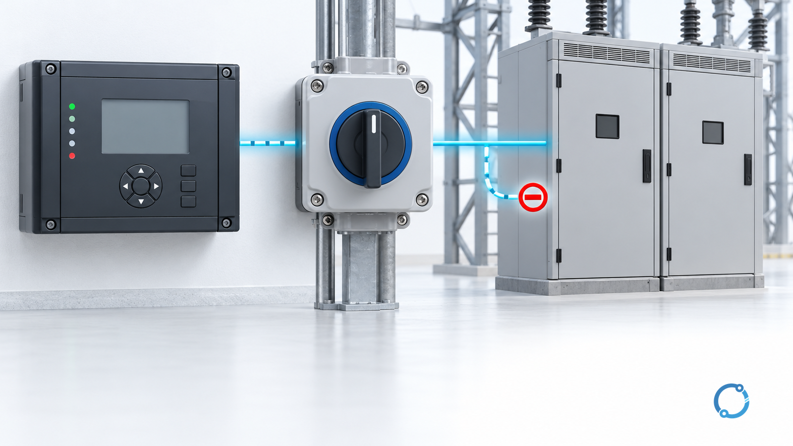
An 86 lockout function retains a protection action until an authorized reset. Design it by specifying which causes latch it, which equipment it trips, which closing paths it blocks and who may release it. A device marked “86” is not evidence that every required output works or that the scheme has acceptable independence.
This guide concerns substation protection and control. It is a functional-design and acceptance framework, not a terminal wiring diagram. An 86 protection lockout is also not personnel lockout/tagout: its operated state does not establish electrical isolation or make equipment safe to touch.
Define the latched state before drawing contacts
IEEE C37.2-2022 provides power-system device-function nomenclature. Use the project naming convention to distinguish separate lockouts and the equipment each one owns. Numbering supports communication; it cannot define the entire protection philosophy.
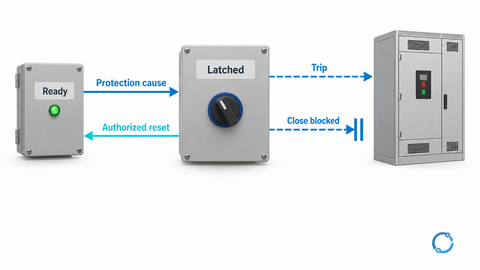
Draw a state model with at least “ready,” “operated/latched” and “reset permitted.” A valid initiating protection action takes the function from ready to latched. The initiating signal disappearing does not itself establish that the equipment may return to service. Reset permission is a controlled decision supported by investigation, corrected conditions and the site’s operating authority.
Specify what persists in the latched state. Common scheme objectives include tripping a defined breaker group and inhibiting its closing paths. The exact implementation may use electromechanical contacts, numerical logic or a combination. Do not assume that all implementations retain state identically after loss of auxiliary power; require documented behavior and an acceptance test for the chosen design.
Allocate causes and effects explicitly
Create a matrix from the protected zone and approved protection philosophy. Keep alarm-only events, ordinary trips and lockout-initiating events distinct. A severe-sounding alarm name is not enough to justify latching, and a convenient spare contact is not a reason to combine unrelated zones.
The following is a hypothetical allocation example, not a recommended universal transformer scheme:
| Defined input | Intended lockout action | Output to verify | Reset evidence |
|---|---|---|---|
| Approved transformer-zone protection trip | Latch the assigned transformer lockout | Every breaker listed for that zone and every required close inhibit | Fault investigation and authorized equipment release |
| Approved upstream breaker-failure action | Latch the specifically assigned isolation function, if required by the philosophy | The wider breaker group stated in that scheme | Breaker-failure cause resolved and topology reviewed |
| Monitoring alarm only | No lockout unless the approved logic expressly requires it | Alarm routing without unintended trip or block | Alarm procedure, not an invented trip/reset sequence |
| Authorized reset request | Reset only when the defined permissions are satisfied | Latch, indications and inhibit outputs return to their specified states | Named authority and documented permission conditions |
For every actual row, identify the source relay output, lockout identity, destination breaker or process output, indication and test method. Verify all closing origins: local control, remote control and any automatic sequence applicable to the installation. A block that only reaches one close path can leave another path available.
Reset must not inadvertently issue a close command. If restoration includes automatic control, document its behavior separately so that reset cannot silently become permission for unexpected re-energization.
Preserve the intended protection independence
A shared lockout can simplify the drawing while creating a common failure. Check whether otherwise independent protection channels now depend on one lockout coil, shaft, logic instance, auxiliary supply or contact bank. Conversely, adding multiple lockouts does not create independence if their common feed or common output still defeats both paths.
Use a short failure-state review:
| Failure or condition | Design question |
|---|---|
| Loss of operating supply | Can a valid trip still reach the required equipment, and is the unavailable function reported? |
| One output contact fails | Which breaker or close path is affected, and how is that failure detected? |
| Reset input is stuck or continuously asserted | Can the initiating protection action be masked or the latch immediately released? |
| Numerical device restarts | Are retained state, startup outputs and reset permissions defined? |
| Maintenance isolation is left in test position | Which protection functions are unavailable, and how is restoration confirmed? |
This review does not prescribe that every station duplicate every component. The protection reliability objective and actual common nodes determine what must be independent.
Contact make/break duty and operating-coil requirements remain device-specific. Include every added lockout or interposing contact in the actual trip-path voltage and duty assessment. The separate substation trip-circuit design guide covers that electrical path; the present page addresses the latched scheme around it.
Test the effects, not only the handle position
Reclamation FIST 3-8, Section 9 documents how coils, contacts, wiring and mechanical binding can defeat lockout actions. It emphasizes controlled electrical functional testing, including the as-found condition and actual downstream effects. A moving handle or changing indication cannot establish that every contact operated.
Build the test plan around the approved matrix. For each initiating cause, record the lockout response and every assigned output. Include close inhibition, alarms and event indication, not only the easiest breaker to observe. Where a test cannot operate the actual destination, state the substituted boundary and the remaining verification needed. Never describe a simulated indication as an end-to-end breaker trip.
Tests can trip operating equipment or disable protection. Authorized personnel must define switching, isolation, temporary test conditions, system consequences and restoration before starting. Do not improvise jumpers in an in-service scheme. Retain as-found evidence before cleaning, adjustment or repair changes the condition being investigated.
Make reset authority and restoration auditable
The operating procedure should identify who may authorize reset, what evidence they must review and how the action is recorded. Local versus remote reset is a design decision with operational consequences. Neither is inherently justified by convenience alone. Specify what happens if an initiating signal remains active, and validate that behavior against the protection objective.
After a real operation, use the breaker-trip troubleshooting workflow to reconstruct the event before considering restoration. Preserve the original cause, sequence and breaker states even if the latch is subsequently reset.
The release package should contain the cause-and-effect matrix, state/reset specification, common-failure review, actual contact/coil assessment, functional results and restored test-switch positions. Maintenance intervals must follow the applicable program. The Reclamation FIST publication index specifically notes that its scheduling manual supersedes equipment-specific intervals; do not copy an old interval as a universal industry rule.