
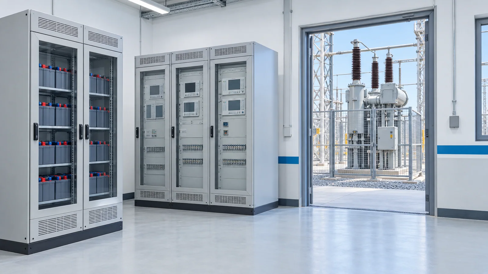
A breaker trip circuit is successful only if a protection decision reaches the correct trip coil with enough energy under the least favorable credible control-power condition, and the breaker then opens. Start the design by drawing the complete command path, calculating worst-case coil-terminal voltage and checking that a single plausible failure will not defeat the protection philosophy. Nominal battery voltage, relay output rating and a schematic “trip” arrow are each insufficient alone.
This guide concerns control circuits for AC high-voltage substation breakers, commonly supplied by station DC. It is not a universal trip-wiring diagram or a substitute for the breaker’s specified control requirements. IEEE C37.11-2022 covers the breaker’s basic electrical control elements above 1 kV, but explicitly does not cover protective relaying or special interlocking. Those interfaces require their own design and testing.
Draw the entire trip path
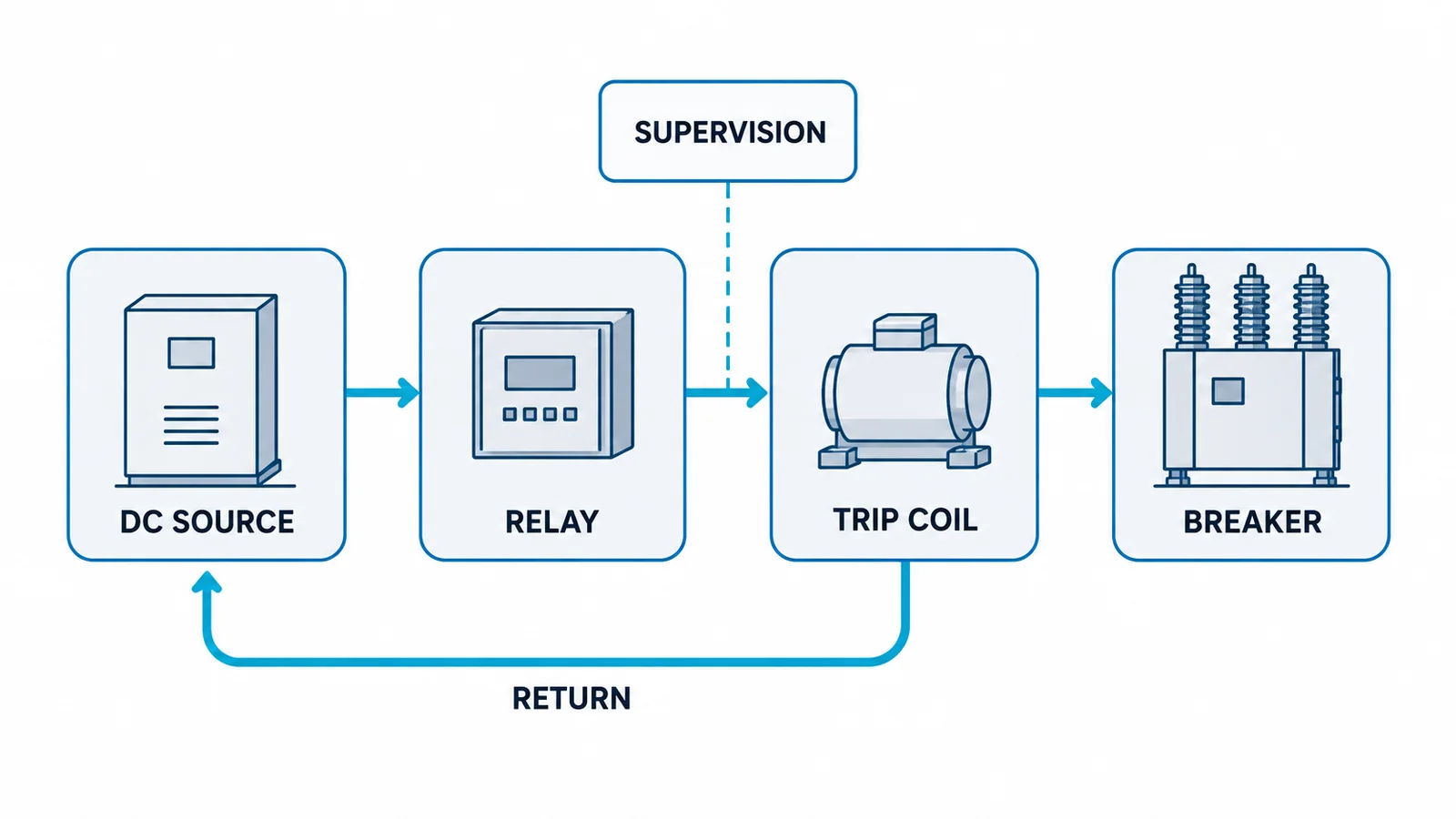
Trace the route from battery/charger and DC distribution through fuse or breaker, terminal blocks, relay output or interposing relay, lockout/interlock contacts where applicable, cable, breaker auxiliary contact and trip coil, then back to the DC return. Document the status of each contact in normal, alarm and trip states. Include both trip coils if installed; show whether they have truly independent feeds or only appear redundant on paper.
List every permitted origin of a trip command: protection relays, local manual trip, remote control, lockout device, breaker-failure scheme and any process interlock. A trip matrix should identify which origins operate which coils and which breakers. Use the project’s device naming convention; IEEE C37.2-2022 standardizes device-function numbers and acronyms, but a number on a drawing does not prove circuit behavior.
Check the low-voltage case at the coil
The limiting case may be near battery end of discharge, with a charger unavailable, coincident DC loads and elevated conductor resistance. Obtain the DC source’s minimum design voltage under the actual trip duty, not merely the nameplate voltage. Battery capacity, charger and distribution design need a project-specific study.
For a simplified steady-current check:
Vcoil = Vsource,min − Itrip × (Rfeed + Rreturn + Rcontacts + Rfuse)
Compare the result with the breaker’s specified coil operating range at the relevant temperature and duty. Also verify relay and interposing-contact make/break ratings for the DC inductive load, trip-coil inrush, fuse coordination and actual wiring. A steady-state Ohm’s-law calculation does not replace dynamic coil or battery performance data.
Illustrative budget, not a design value: assume the minimum DC distribution voltage under the trip event is 105 V, the prospective coil current is 5 A, and combined feed/return/contact resistance is 1.2 Ω. The calculated coil voltage is 105 − 5 × 1.2 = 99 V. If the exact breaker’s minimum required coil-terminal voltage under that condition were 100 V, this arrangement would fail the screen despite a nominal system nameplate above 100 V. The example numbers are assumptions; obtain actual battery, coil, wiring and contact data before deciding.
High-voltage cases matter too: charger boost or other operating modes must stay within the coil and relay-input upper limits. Consider whether multiple simultaneous trip operations, breaker failure or autoreclose can change the duty. Do not size a battery or charger from the one-coil example above.
Design out single points of failure deliberately
Two trip coils do not provide meaningful diversity if both depend on one fuse, one battery section, one relay output, one common terminal block or one DC return. Conversely, duplicating everything can create maintenance and testing complexity. Define the required reliability objective, draw the common nodes, and check each credible single failure against the station’s protection philosophy.
Questions worth recording:
- Does a blown DC fuse disable one or both trip paths?
- Does a breaker auxiliary contact open the coil circuit at the intended time?
- Can an interposing relay weld, fail to pick up or exceed its DC contact duty?
- Can a lockout device or test switch block an otherwise valid trip?
- Are polarity, grounding and DC earth-fault monitoring consistent with station practice?
- Are local and remote indications independent evidence of breaker opening, or only of a trip command?
The answer is circuit-specific. Do not claim that any one topology is universally required by IEEE C37.11; its scope is narrower than the whole protective scheme.
Supervise what you can actually detect
Trip-circuit supervision may detect loss of supply or an open path under certain breaker states. It must be designed around the normal open/closed state of auxiliary contacts and the supervision device’s sensing current. A healthy indication can miss a failure outside the supervised portion of the path; an alarm can also arise from an intentional test-switch or maintenance position. Mark supervision injection and sensing points on the schematic and document the blind spots.
Monitor battery/charger, DC bus, distribution fuses and earth faults separately where the design requires them. Label alarms so operators can distinguish an unavailable trip path from a mere command or indication fault. For North American bulk-electric-system assets in scope, NERC PRC-005-6 addresses protection-system maintenance programs; applicability must be determined by the responsible entity and does not by itself supply a trip-circuit design recipe.
Acceptance and maintenance test matrix
| Test or review | Evidence to capture | Failure it can reveal |
|---|---|---|
| Drawing walk-down and point-to-point continuity | Actual terminals, polarities and devices | Wiring or documentation mismatch |
| Minimum-DC-voltage calculation and measured drop where permitted | Battery duty, loop resistance, coil voltage | Coil undervoltage in worst case |
| Each authorized trip origin | Command, coil operation, breaker opening and indication | Logic or contact-path failure |
| Trip-circuit supervision fault simulation | Alarm behavior in defined breaker states | Blind spot or nuisance alarm |
| Loss of one DC feed or fuse, when safe and approved | Surviving path and alarm | Hidden common-mode dependence |
| Post-maintenance end-to-end functional test | Trip event record, measured timing and breaker status | Disconnected or reversed path |
Testing a live substation trip scheme can open a breaker and disturb the power system. Only authorized, qualified personnel should perform approved tests under the station’s switching, isolation and restoration procedure. A relay “trip” LED is not evidence that the breaker opened. The handoff is a schematic, voltage budget, trip matrix, supervision boundary and witnessed functional-test record—not a rule-of-thumb wire gauge.