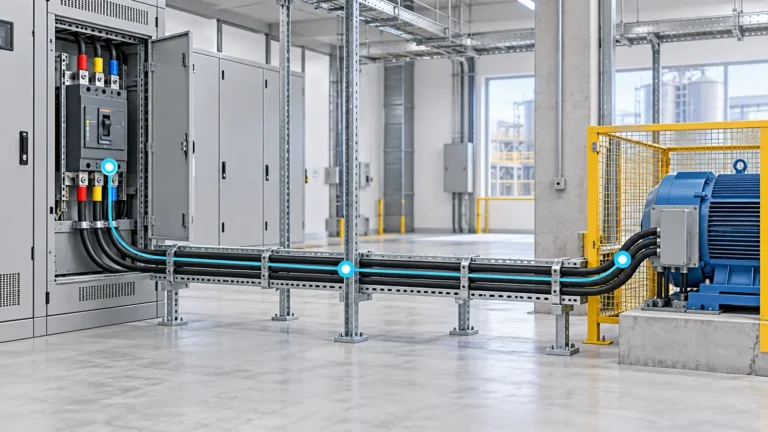
Wiring, Cables & Busbars
Cable Sizing for Circuit-Breaker-Protected Feeders: Six Verification Gates
For an LV feeder protected by a circuit breaker, choose a cable whose corrected current-carrying capacity covers the load and the breaker’s…

OHELE topic hub
Conductor sizing, cable systems, busbars, terminals, joints and panel wiring.
Wiring, cables and busbars form the current path between a source, protective equipment and a load. Their selection cannot be reduced to a current rating table. Conductor material, cross-section, insulation, installation method, grouping, ambient temperature, fault current, voltage drop, jointing, termination and support all affect whether the path remains safe and functional throughout its service life.
The reading path begins with cable sizing for a circuit-breaker-protected feeder. A useful calculation checks current-carrying capacity, protective-device compatibility, voltage drop, short-circuit withstand and installation conditions. Each check asks a different question. A cable that carries the normal load may still be unable to tolerate a fault for the time required by the upstream device, or may create excessive voltage drop at the far end of a long run.
The installation articles then examine how the cable is terminated and supported. A correctly sized conductor can fail at a termination because of poor preparation, incompatible materials, inadequate creepage, thermal cycling, moisture or mechanical strain. Medium-voltage terminations add stress control and insulation considerations that do not appear in a simple low-voltage joint. Cable fire performance introduces another boundary: a product classification, an installation method and an actual site condition are not interchangeable.
Busbar material is chosen as part of a complete current path. Copper and aluminium differ in conductivity, mass, expansion, joint behaviour, corrosion response and fabrication requirements. Ampacity must be evaluated with the enclosure, ventilation, ambient temperature, plating, support and fault-current conditions of the actual assembly. A bare-metal comparison can be useful for understanding, but it is not a substitute for a verified busbar design.
Terminal blocks and panel wiring determine how conductors are organised, identified and maintained. A terminal block may have a nominal wire range, a current rating and a rail footprint, yet still be wrong for a circuit because of conductor class, voltage spacing, PE/PEN duty, accessories, short-circuit context or approval requirements. The connection interface must also be serviceable. Maintenance access, marking and a record of the installed configuration are part of the electrical design.
Use this hub according to the current path you are evaluating. Start with the cable-sizing pillar for a feeder. Move to terminations and fire performance for installation questions, busbars for high-current distribution, and terminal blocks for panel interfaces. The articles are written for engineers, electricians and purchasers who need to compare products and proposals. They do not replace an approved installation design, manufacturer torque instructions, local code requirements or the verification procedure for the completed circuit.
Construction quality is part of the electrical calculation. A conductor route that changes the grouping, a terminal installed with the wrong conductor class, or a busbar joint that cannot be inspected can alter the thermal and fault behaviour of the finished assembly. For that reason, the guides distinguish a product’s declared range from the installed connection that must be verified. They also distinguish a visual fit from an approved interface. When a replacement part is proposed, the decision should record the function, conductor, current, voltage, environment, accessories and approval basis rather than relying on a similar-looking body or DIN-rail profile.
The final record should identify the installed conductor, terminal or busbar configuration and the checks completed after assembly. That record supports maintenance, fault investigation and future replacement without relying on an undocumented assumption about what was originally fitted. It should also show which product, accessory and installation conditions were approved for the actual duty, so a later substitution is checked against evidence rather than appearance. A clear record is part of the installation quality, not paperwork added after the work, and it should remain available to the person who next opens the panel.
Wiring, Cables & Busbars
For an LV feeder protected by a circuit breaker, choose a cable whose corrected current-carrying capacity covers the load and the breaker’s…
Cable size depends on the expected current, installation method, ambient and grouping conditions, voltage drop, protective-device behaviour, short-circuit withstand and applicable installation rules. The largest requirement from those checks can govern the final selection.
Compare the complete current path, including conductivity, required cross-section, mass, support, joint system, thermal expansion, environment, losses and fabrication. A conductivity ratio alone does not establish equivalent ampacity or a safe connection.
The block must match conductor type and size, voltage and current duty, connection function, rail space, accessories, environmental conditions, approvals and the panel's short-circuit context. The installation must also remain accessible for inspection and maintenance.
Only when the terminal product, conductor combination and installation are explicitly suitable and approved for that arrangement. A terminal that visually accepts two wires does not prove that the connection is rated, tested or compliant.
Busbar can provide a compact, high-current distribution path with predictable support and jointing. Cable can be more flexible in routing and connection. The choice depends on current, fault level, space, enclosure, maintenance, voltage drop and installation requirements.
Newest first
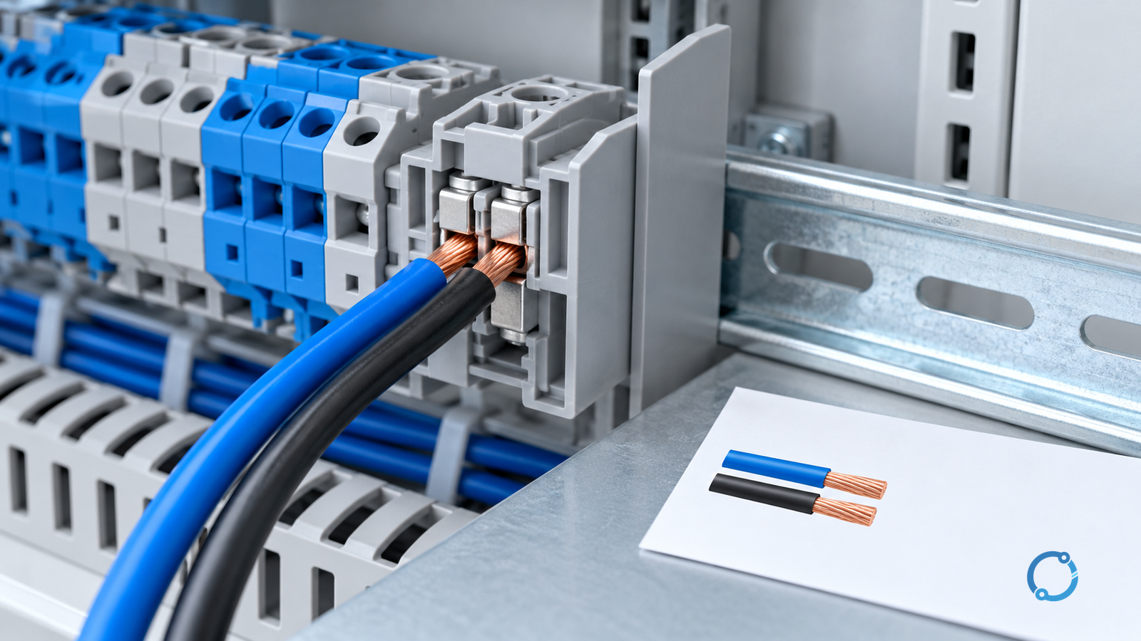
Two conductors can share one terminal block only when the exact terminal arrangement is rated and approved for that conductor pair. That sentence deliberately separates two conditions that…
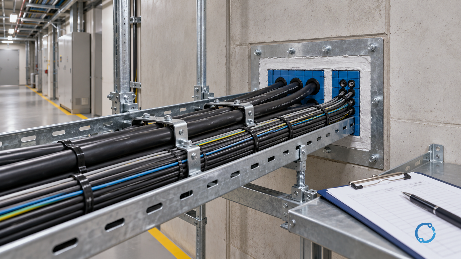
“Fire-rated cable” is an incomplete description. It does not say what hazard was tested, what performance was demonstrated or whether the installed route can maintain that performance. Cable…
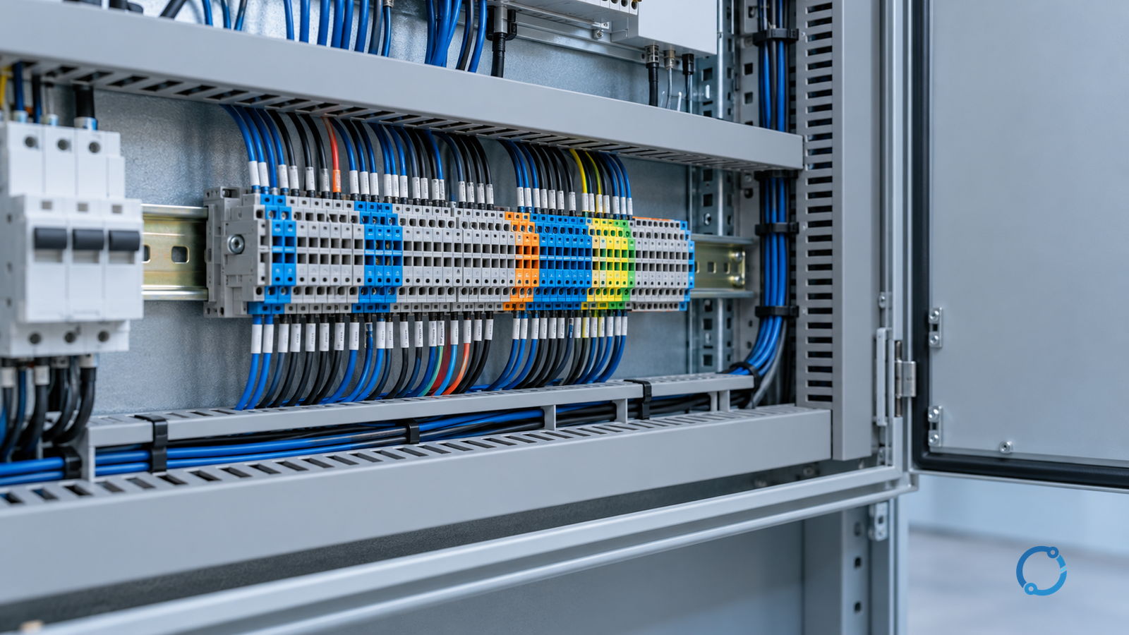
A serviceable terminal strip lets a qualified person identify the right circuit, reach its connection, work on it with the required isolation in place, and restore the correct…
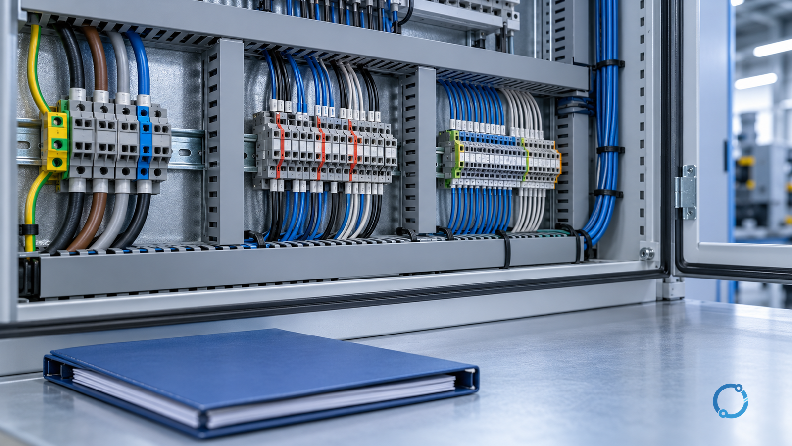
Separate terminal blocks by the hazards and dependencies of each circuit, not by the words printed above a DIN rail. A useful layout keeps power conductors away from…
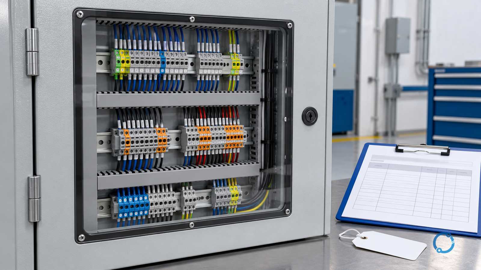
A discolored or unusually warm terminal block is a symptom, not a diagnosis. The heat may originate at the conductor-to-terminal interface, somewhere else in the same current path,…
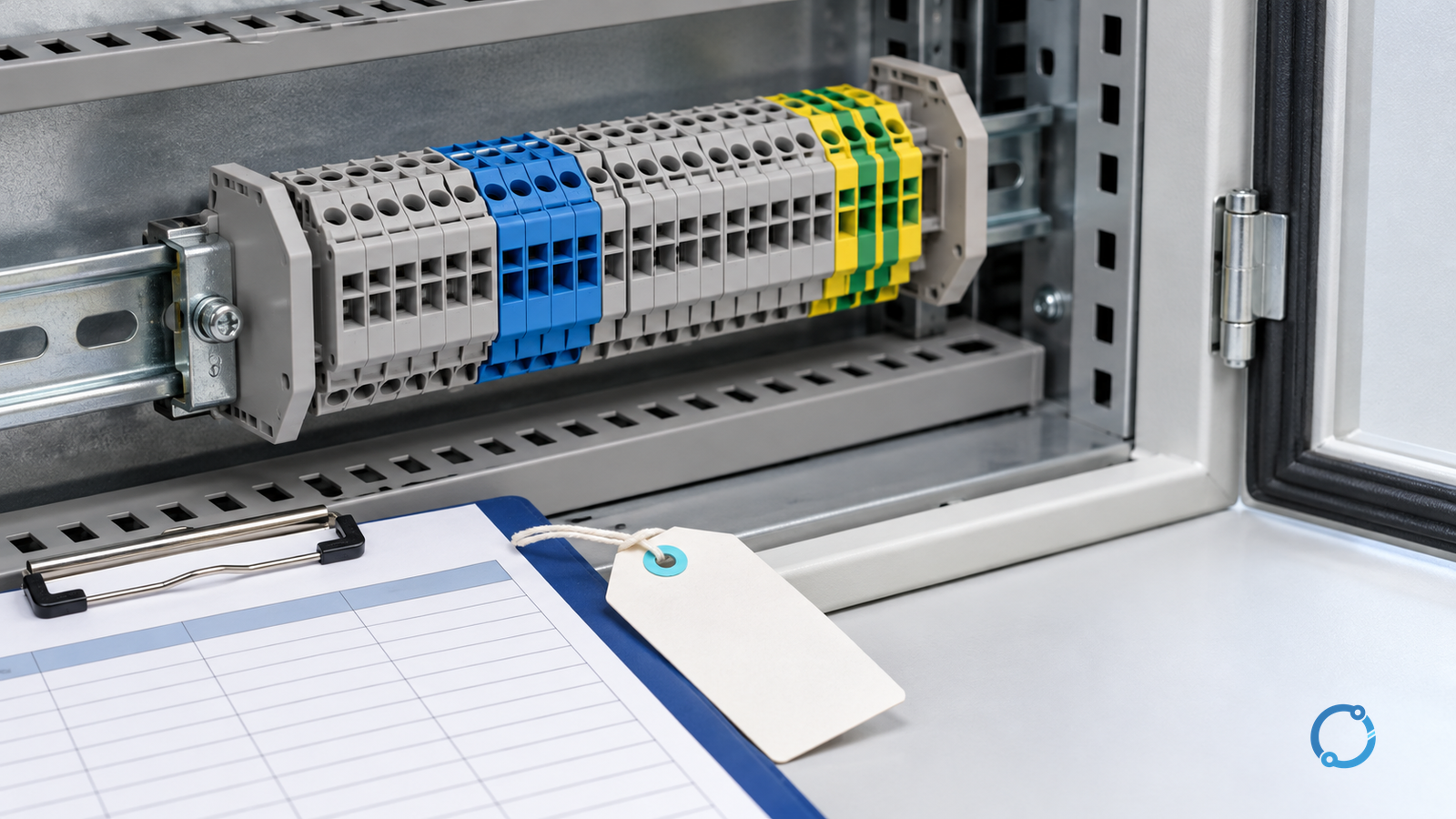
A terminal block is a safe replacement only when the proposed part preserves the complete installed duty: circuit function, conductor interface, electrical and thermal capability, physical access, accessory…
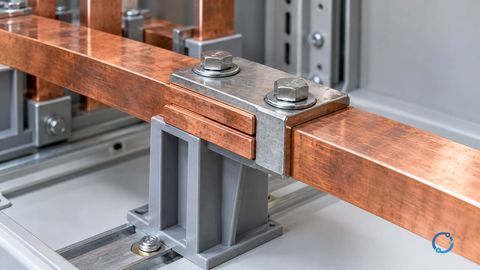
A hot copper busbar joint is not automatically a loose joint. Its temperature is the result of the current it carries, the ambient conditions around it, the heat…
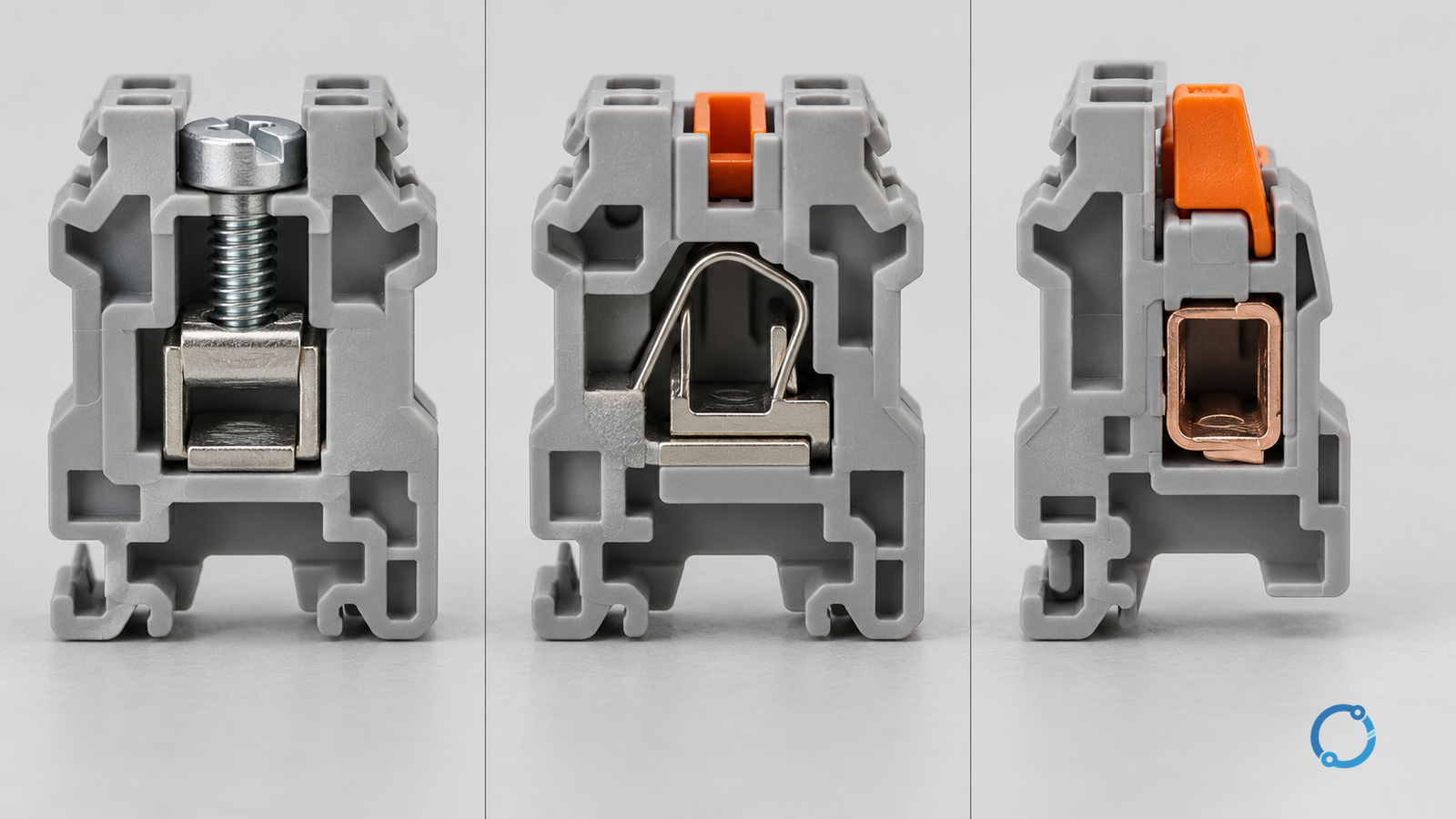
There is no universal winner among screw, spring-cage and push-in terminal blocks. The useful comparison starts with the conductor and the service duty, then evaluates the complete connection…
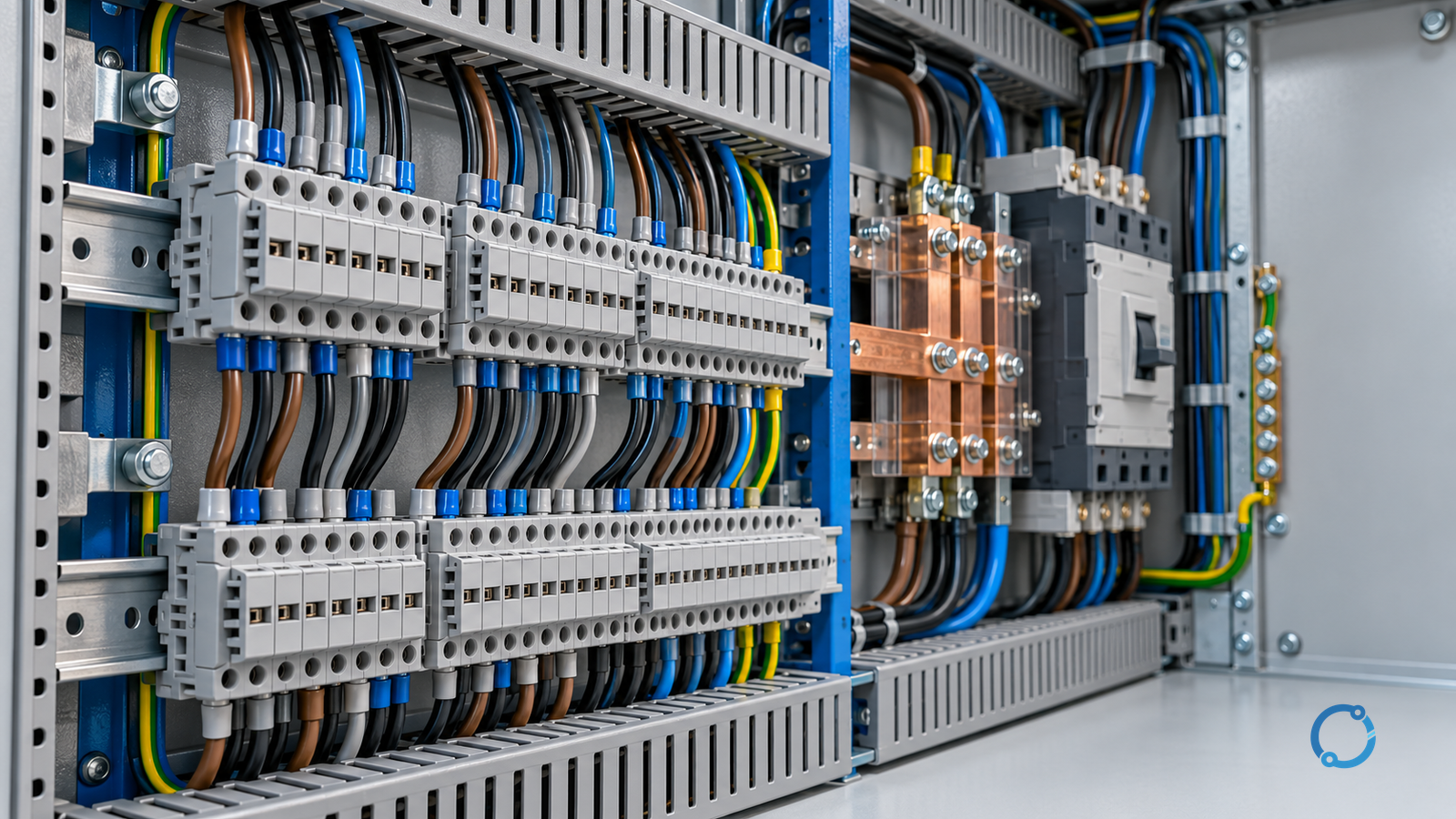
A terminal block does not hold a panel’s short-circuit current rating (SCCR) by itself, and buying a listed terminal block does not make an assembly compliant. The rating…
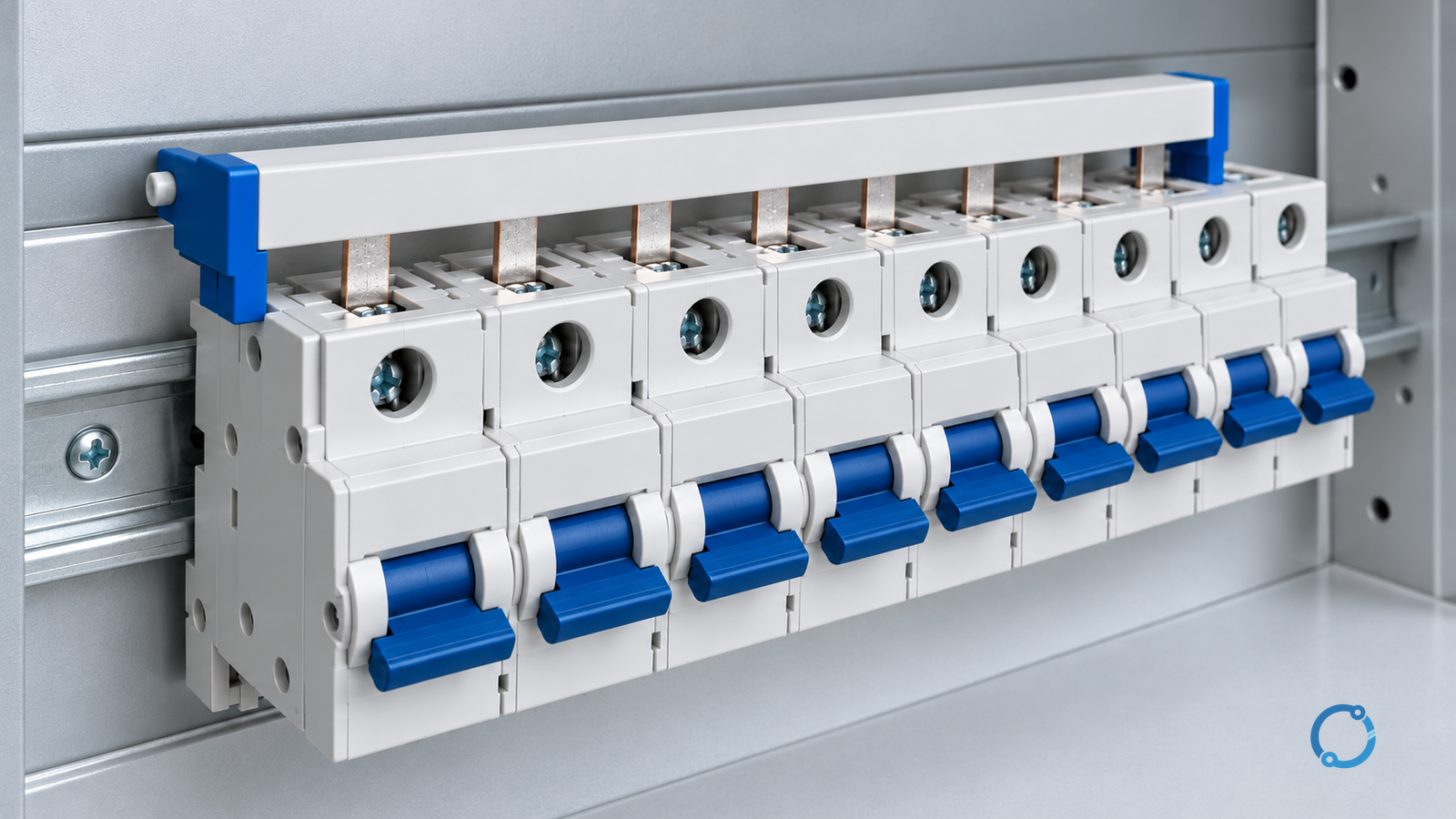
Use a comb busbar when the breaker family, pole pitch, pole count and current rating are fixed, the busbar is declared for that exact breaker, and the row…