

A terminal block is a safe replacement only when the proposed part preserves the complete installed duty: circuit function, conductor interface, electrical and thermal capability, physical access, accessory system, environmental performance, product and panel approvals, and the evidence needed to verify the change. A matching silhouette, wire range, colour or DIN-rail profile is not enough.
That distinction matters most when the original model is obsolete. The old catalogue page may have disappeared, the marking may be worn off, and the panel drawing may show a part number without the terminal accessories that were later added. In that situation, a “cross-reference” should not mean finding the most similar current part. It should mean reconstructing the requirements from the installed circuit and proving that a candidate meets them.
This guide is for qualified panel designers, maintenance engineers and technical buyers working on industrial low-voltage equipment. It provides a replacement-planning framework, not a universal model-to-model lookup. It does not authorize energized work, and it does not replace the panel manufacturer’s instructions, the applicable product standard, the local electrical code or the approval process that governs the equipment.
Start with a replacement decision, not a shopping search
The first useful output is not a candidate part number. It is a replacement decision record that states what the original terminal does and what the new terminal must preserve. The record should let another qualified person review why a candidate was accepted, why another was rejected, and which facts remain unproven.
Use four levels of evidence:
- Observed facts: what is visible on the installed assembly, circuit drawing, bill of materials and maintenance record.
- Verified requirements: the conductor, voltage, current, function and environmental conditions established from approved documentation or measurement by a competent person.
- Product evidence: the candidate manufacturer’s data, instructions and declarations for the exact part and accessories.
- Approval evidence: confirmation that the candidate can be used in the equipment under the applicable panel design, certification and change-control rules.
Do not collapse these levels into one claim. A catalogue’s statement that a product family is covered by a standard is not proof that a particular catalogue number is approved for the panel. A technician’s measurement is not a substitute for the design record if the circuit may have been altered. A supplier’s statement that two parts are “equivalent” is not an approval decision unless the evidence and authority behind that statement are clear.
Reconstruct the installed terminal before comparing candidates
The replacement process begins with the terminal assembly as a system. The original block may carry one conductor or several, provide a feed-through connection, join a protective conductor, hold a fuse, distribute a signal, isolate a test point or support another accessory. Those functions are not interchangeable.
Build a short installed-system sketch before opening a catalogue:
- identify the circuit, panel section and source of supply;
- mark the terminal’s location in the conductor path;
- record what is connected above and below it;
- identify any cross-connection, bridge, shield connection, test socket, fuse holder or marker system;
- note whether the terminal is part of a protective-conductor or PEN path;
- record adjacent components and the access needed for inspection and maintenance;
- photograph or trace the installed arrangement without relying on the old label alone.
The sketch does not need to be a construction drawing. It needs to preserve the relationships that a replacement could disturb. If the terminal is one block in a long rail, for example, the replacement may change the width, end-plate arrangement, jumper pitch, marking carrier or cover. The electrical function may remain the same while the assembly around it no longer fits or cannot be inspected.
The existing terminal-block selection guide for electrical panels explains the forward selection process when the circuit is being designed. This page handles the reverse case: the design exists, but the original part does not. The terminal-block replacement checklist becomes useful after a candidate and its supporting evidence have been identified.
The eight gates of a defensible cross-reference
The replacement decision can be organized into eight gates. A candidate must pass every gate that applies to the installed function. The result is not an average score; one unresolved safety, conductor or approval condition can stop the replacement.
Gate 1: circuit function and protective-conductor role
First establish what the terminal does. A feed-through terminal block, a protective-conductor terminal block and a fuse terminal block are different product families with different requirements. IEC 60947-7-1:2025 covers industrial terminal blocks with screw-type or screwless clamping units for copper conductors within its published scope. IEC 60947-7-2:2009 addresses protective-conductor terminal blocks, including the PEN function within its scope. IEC 60947-7-3:2009 covers fuse terminal blocks.
Those scopes help classify the product, but they do not decide whether two catalogue items are interchangeable. A feed-through terminal cannot be used as a protective-conductor terminal merely because it fits the same rail. A fuse terminal replacement must preserve the fuseholder, fuse type, circuit protection function and associated approvals. A test-disconnect or multi-level terminal may carry more than one circuit relationship that is not visible from the front.
The panel drawing should identify the terminal function, but drawings are sometimes incomplete. Where the function is uncertain, trace the circuit under the site’s safe isolation procedure and involve the responsible engineer. Do not infer a protective function from a green-yellow colour alone; local conventions and incorrect modifications exist.
Gate 2: conductor material, size, class, count and direction
The conductor interface is often the first real incompatibility. Record:
- conductor material and, where relevant, the exact conductor construction;
- nominal cross-sectional area and the range of sizes actually used;
- flexible, stranded or solid conductor class;
- number of conductors per clamping point;
- whether two conductors share one side or the terminal is a multi-conductor type;
- conductor entry direction and the space needed for ferrules or cable lugs;
- strip length, clamping method and any approved accessories;
- whether the conductor is copper, aluminium or another material.
The public scope of IEC 60947-7-1 is centered on copper conductors. That does not mean every terminal outside that scope is unsuitable; it means the replacement must be evaluated under the correct product scope and the manufacturer’s instructions. Do not assume that a terminal rated for a copper wire range is approved for an aluminium conductor of the same nominal area.
The terminal-block markings guide for UL and IEC systems is useful for separating product-family information from the actual conductor and approval markings. The screw, spring and push-in comparison explains why the clamping method and the permitted conductor preparation belong in the same decision.
Gate 3: voltage, current, frequency and real load
Do not copy the largest number printed on the old block into a replacement request. Reconstruct the duty:
- rated and actual operating voltage;
- circuit voltage to earth and between conductors;
- continuous and cyclic current;
- ambient temperature and enclosure temperature;
- number of loaded circuits and adjacent heat sources;
- frequency, harmonics or special waveform where relevant;
- short-time, starting or fault-related current exposure;
- whether the terminal is in a current-transformer, control, signal or power circuit.
A terminal’s current rating is not a single property that survives every installation condition. Product standards and manufacturer data define the test basis, derating and accessories that apply. The terminal current-rating and actual-load guide and the derating-curve guide explain why the catalogue headline and the installed thermal duty must be checked separately.
If the old part has no reliable rating, obtain the circuit design current and the approved panel basis. A measured current during a short observation is not proof of the maximum continuous or cyclic duty. A larger replacement can also be unsuitable if it changes spacing, busbar geometry, enclosure clearance or the ability to close a barrier.
Gate 4: dimensions, rail, wiring access and adjacent equipment
Rail compatibility is necessary but narrow. IEC 60715:2017 addresses standardized mounting-rail dimensions and functional requirements. It does not establish terminal equivalence. Two blocks can mount on the same rail while differing in width, height, depth, terminal entry, clamping access, end-stop position and finger clearance.
Measure the installed envelope, not only the rail:
- rail type and the exact mounting method;
- block width and pitch across the assembly;
- height above the rail and depth behind the panel front;
- conductor entry and screwdriver access from the intended side;
- space for ferrules, cable lugs, covers and test probes;
- clearance to enclosure walls, busbars and adjacent devices;
- end plate, end stop and partition requirements;
- label orientation and visibility after the door is closed.
A replacement that fits on the rail but blocks a terminal screw or prevents the cover from closing is not a successful replacement. The DIN-rail space and terminal-block layout guide covers the dimensional consequences in more detail.
Gate 5: the complete accessory and marker system
The terminal block is usually part of an accessory stack. Cross-reference the system, not only the centre block. Check:
- end plates and partitions;
- end stops and mounting feet;
- jumper bars and the number of positions they bridge;
- test sockets, disconnects and fuse carriers;
- covers, shrouds and touch protection;
- marker carriers and label sizes;
- shield or protective-conductor connections;
- mounting screws, rail adapters and locking components.
Accessories can determine the electrical function, the achievable spacing or the ability to maintain the assembly. A new centre block with the same wire range may not accept the installed jumper, marker card or test accessory. Even when individual parts fit mechanically, the resulting combination must still be covered by the manufacturer’s product data and the panel design.
The mixed terminal-block bill-of-materials release guide is relevant when one panel uses more than one terminal family. Mixed families can be legitimate, but the change record must identify which accessories are compatible and which are not.
Gate 6: pollution, insulation and environmental duty
The enclosure environment is part of the terminal specification. Record:
- expected pollution degree and condensation risk;
- dust, moisture, oil mist, salt, chemicals or cleaning agents;
- ambient and internal enclosure temperature;
- ultraviolet exposure where the terminal is outside a protected enclosure;
- vibration, mechanical impact and conductor movement;
- flame, smoke or material requirements imposed by the equipment;
- spacing to live parts and accessible surfaces;
- the need for covers, partitions or sealed entries.
IEC 60664-1:2020+AMD1:2025 provides the insulation-coordination framework for low-voltage equipment within its scope, including clearance, creepage and solid-insulation concepts. It does not provide one universal terminal-strip clearance value that can be copied into every panel. The pollution-degree selection guide explains how the environment changes the verification question.
An old terminal that has worked for years is not automatically suitable for a changed enclosure, a new cleaning regime or a higher altitude. Replacement is an opportunity to discover that the original installation record was incomplete.
Gate 7: product approval, panel approval and short-circuit context
Keep four approval questions separate:
- Is the candidate within the applicable product standard’s scope?
- Does the manufacturer’s evidence cover the exact part and accessory combination?
- Is the candidate acceptable under the panel or equipment approval?
- Does the complete assembly remain suitable for the available fault current and protection?
The existence of IEC 60947-1:2020 or a terminal-family standard does not prove that a product is certified, listed or approved for a particular panel. A standard may define requirements and tests without making a compliance claim for a catalogue item. The terminal-block SCCR and UL 508A panel guide explains why short-circuit current rating and panel approval belong to the assembly, not just the terminal’s headline current.
The panel manufacturer’s file, the certification body’s conditions and the project’s approved-components list may be more restrictive than the terminal catalogue. Where the installed panel is field-modified, the owner’s change-control process decides who can accept the substitution and what documentation is required.
Gate 8: installation verification and change record
The final gate is evidence that the installed result is correct. Before release:
- verify the candidate part and accessory numbers against the approved record;
- confirm the conductor preparation and clamping method;
- verify the terminal function, polarity and protective-conductor path;
- inspect spacing, covers and touch protection;
- confirm torque or tooling only from the approved product instructions;
- perform the required continuity, insulation or functional checks under the site procedure;
- update the drawing, bill of materials and maintenance record;
- retain the old part, photographs and rejected candidates where the change record requires them.
The sign-off should identify who selected the part, who reviewed the technical evidence and who authorized the change. A successful visual fit is not a release.
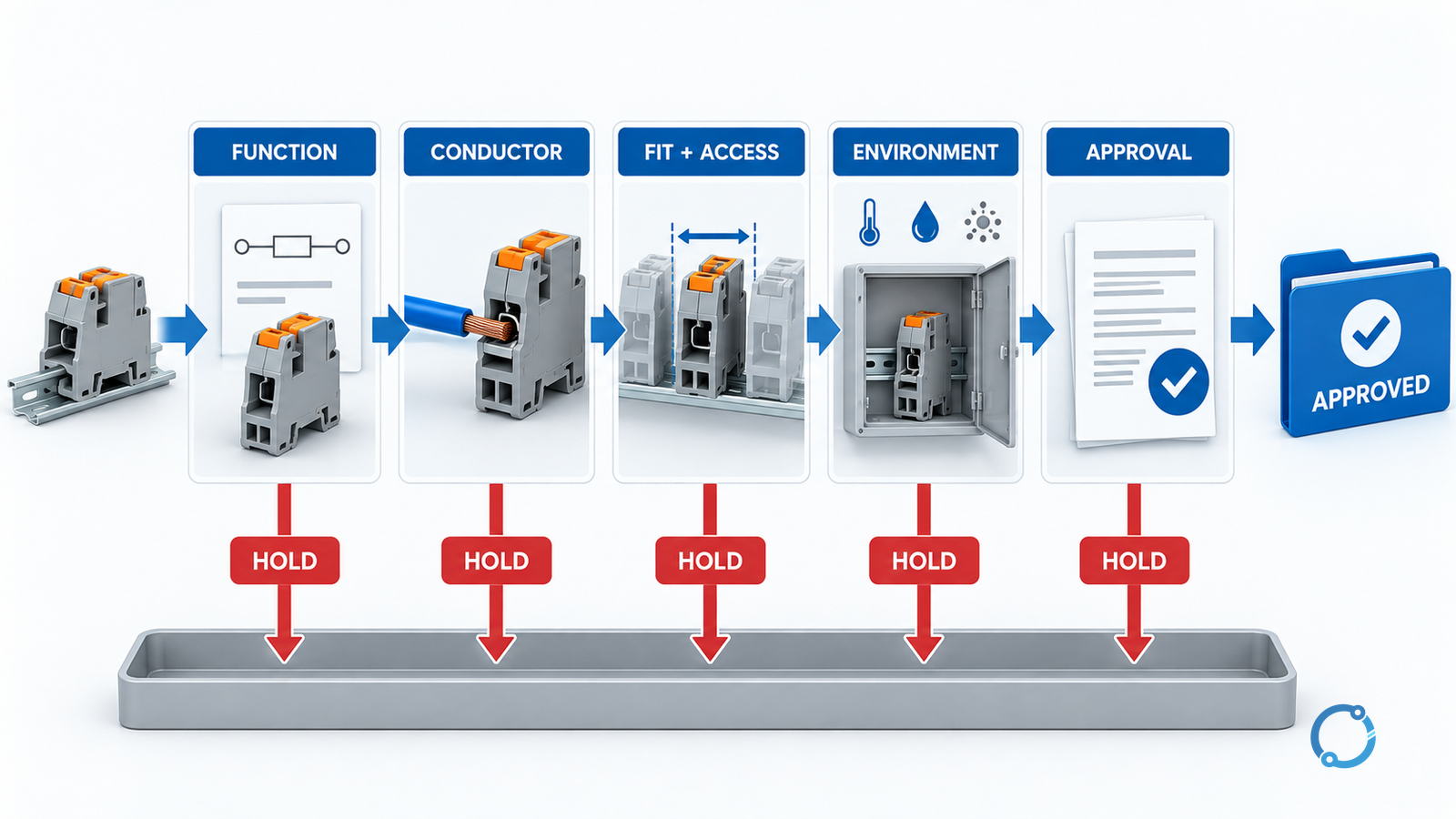
Use one replacement matrix for every candidate
The matrix below turns the eight gates into a reviewable record. Add product-specific fields rather than deleting a gate because the answer is inconvenient.
| Decision field | Installed requirement | Candidate evidence | Status |
|---|---|---|---|
| Function | Feed-through, PE/PEN, fuse, test, multi-level or signal function | Exact product type and manufacturer description | Verified, unresolved or rejected |
| Conductor interface | Material, size, class, count and entry direction | Clamping range, conductor preparation and permitted combinations | Verified, unresolved or rejected |
| Electrical duty | Voltage, current, frequency, load profile and temperature | Product rating basis, derating and accessory conditions | Verified, unresolved or rejected |
| Geometry | Rail, width, height, depth and access | Exact dimensions and installed arrangement | Verified, unresolved or rejected |
| Accessories | End plates, jumpers, markers, covers and test parts | Compatible catalogue numbers and assembly evidence | Verified, unresolved or rejected |
| Environment | Pollution, moisture, temperature, vibration and cleaning | Product and enclosure suitability for the actual conditions | Verified, unresolved or rejected |
| Approval | Product scope, panel approval and fault-current context | Exact declarations, listing and panel conditions | Verified, unresolved or rejected |
| Installation | Tooling, inspection, tests and change record | Approved instructions and completed verification | Verified, unresolved or rejected |
Use three outcomes: verified, unresolved or rejected. Do not use “probably equivalent” as a release status. If the evidence is incomplete, keep the candidate on hold and state the next evidence request.
A bounded example of the decision logic
Consider a fictional control panel with a discontinued feed-through terminal on a DIN rail. The drawing shows a 2.5 mm² stranded copper control conductor, one conductor per side, and a marker carrier. The terminal sits beside a relay, and the panel door closes over the wiring. No protective-conductor function is shown.
A similar current terminal is proposed. It mounts on the same rail and accepts the same nominal wire range. That establishes only a starting possibility. The reviewer still needs to check whether the proposed terminal accepts the installed ferrule, whether the marker carrier fits, whether the new width changes the pitch of the adjacent blocks, whether the door clearance remains adequate, whether the terminal is suitable at the actual enclosure temperature, and whether the panel approval accepts the substitution.
If the original terminal used a bridge that is not present on the new family, the candidate may be rejected even though the centre block fits. If the proposed block has a different touch protection or requires a larger strip length, the installation procedure and training requirement also change. If the old label is missing and the circuit function has not been traced, the process stops at Gate 1.
This example is deliberately ordinary. The purpose of the matrix is to prevent an ordinary replacement from becoming an undocumented design change.
Common cross-reference errors
| Error | Why it fails | Better control |
|---|---|---|
| Matching by DIN rail only | The rail proves mounting compatibility, not electrical or environmental equivalence | Compare all eight gates |
| Matching the old headline current | The installed thermal and accessory conditions may be different | Reconstruct the actual duty and product rating basis |
| Treating “2.5 mm²” as one interface | Conductor class, ferrules and clamping method can change the result | Verify material, class, count and preparation |
| Reusing the old marker or jumper without checking | Accessories can determine spacing, function and approval | Cross-reference the complete accessory system |
| Copying a “similar” catalogue image | Appearance cannot establish approvals or internal suitability | Obtain exact data and product instructions |
| Calling a candidate equivalent before the panel change is approved | The terminal may be acceptable but the equipment approval may not | Separate product evidence from panel authorization |
| Recording a test result without the test setup | A reading does not reproduce itself | Record instrument, circuit state, method and acceptance criterion |
The marking guide can help interpret what is visible on a product, but the markings must be read with the exact model, catalogue data and applicable approval system. OSHA 29 CFR 1910.303(c) is one bounded example of a jurisdiction that explicitly addresses conductor and terminal identification and dissimilar-metal contact. It is a U.S. requirement, not a universal global rule.
Stop conditions for an obsolete-terminal replacement
Stop the candidate evaluation and escalate when:
- the circuit function or protective-conductor role cannot be established;
- the conductor material or permitted termination is uncertain;
- the available fault current, protective device or panel approval is unknown;
- the candidate’s exact model, accessory set or installation instructions are unavailable;
- the replacement changes the enclosure, barrier, busbar or wiring arrangement beyond the approved scope;
- the proposed part relies on a torque, clearance or temperature value that cannot be traced to the approved product data;
- the installed panel has signs of overheating, arcing, loose connections or contamination that require diagnosis before replacement;
- the work would require energized access or a temporary condition outside the site’s safe work procedure.
For an overheating symptom, the terminal is evidence in a larger investigation. The copper busbar joint overheating diagnostic guide is about busbar joints rather than terminal blocks, but it illustrates the same principle: do not replace a part until the current path, heat source and connection condition have been investigated.
What a good cross-reference conclusion contains
A useful conclusion has five parts:
- Installed function: the circuit role, including PE/PEN or fuse status.
- Hard requirements: conductor, voltage, current, temperature, dimensions and environment.
- Candidate evidence: exact part and accessory references, product scope and manufacturer conditions.
- Approval decision: who confirmed compatibility with the panel and the applicable change-control basis.
- Verification and reopening rule: the tests, records and conditions that would invalidate the decision.
That conclusion is more valuable than a list of “equivalent” model numbers because it shows the assumptions and gives the next reviewer a way to challenge them.
The practical rule
An obsolete terminal block can be replaced safely only when the replacement is treated as a system change. Reconstruct the installed function, define the hard requirements, compare the exact candidate and accessory set, and keep product compliance, panel approval and installation verification separate. A rail fit or a similar current rating may start the search; it cannot finish the decision.
Sources
- IEC 60947-7-1:2025: Terminal blocks for copper conductors, published 2025-04-15, edition 4.0.
- IEC 60947-7-2:2009: Protective conductor terminal blocks, published 2009, edition 3.0.
- IEC 60947-7-3:2009: Fuse terminal blocks, published 2009, edition 2.0.
- IEC 60715:2017: Standardized mounting rails, published 2017, edition 2.0.
- IEC 60947-1:2020: Low-voltage switchgear and controlgear general rules, published 2020, edition 5.0.
- IEC 60664-1:2020+AMD1:2025 CSV: Insulation coordination, consolidated edition 3.1.
- OSHA 29 CFR 1910.303(c): Electrical equipment installation and conductor identification, U.S. regulation, page checked 2026-10-26.