
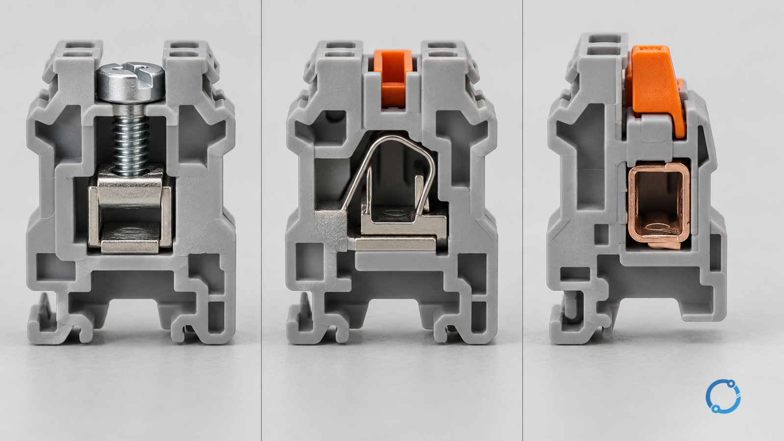
There is no universal winner among screw, spring-cage and push-in terminal blocks. The useful comparison starts with the conductor and the service duty, then evaluates the complete connection system: preparation, clamping force, release method, contact support, inspection access, environmental fit, and the evidence supplied for the exact terminal block.
Choose a screw-clamp terminal when visible tightening, a familiar releasable screw connection, and a defined tightening procedure fit the panel and maintenance model. Choose a spring-cage or push-in terminal when its conductor range, insertion and release method, vibration behavior, and inspection access fit the same duty. These are conditional statements, not rankings. A terminal that is excellent for one conductor and one maintenance routine can be wrong for another.
IEC 60947-7-1:2025 provides the public scope for terminal blocks and test disconnect terminal blocks with screw-type or screw-less-type clamping units primarily intended for industrial or similar use. Its stated conductor range is copper conductors from 0.05 mm2 / 30 AWG to 300 mm2 / 600 kcmil, with circuits up to 1,000 V AC or 1,500 V DC. That scope tells you which family you are evaluating; it does not tell you which terminal will survive a particular panel.
Define the comparison before naming a winner
Use six dimensions for every candidate:
- Conductor preparation and range. Solid, stranded, finely stranded, ferrule use, insulation strip length, and the minimum and maximum conductor size.
- Clamping and release mechanism. How the contact force is created, how the conductor is inserted, how it is released, and what tool or access is needed.
- Current and voltage basis. The exact terminal’s rated values, derating conditions, pollution degree, and installation basis.
- Repeated connection and inspection. Whether the joint can be checked, re-opened, re-terminated, and returned to a verified condition.
- Vibration and loosening control. The mechanical behavior of the clamping system and the installation measures that keep it stable.
- Accessories and system fit. End stops, partition plates, jumpers, test access, marking, DIN-rail space, and compatibility with the enclosure.
If one candidate cannot answer a dimension, keep it on hold. A comparison table with blanks is more honest than a score built from a catalogue headline.
Screw-clamp terminal blocks: visible force, procedural discipline
A screw-clamp terminal uses a screw or stud to apply clamping force to the conductor or a pressure plate. The visible screw gives maintenance staff a direct mechanical action to inspect, but visibility is not the same as verification. The correct result depends on the terminal’s specified conductor range, the correct strip length, the correct clamping position, and the tightening procedure defined for that product.
The strongest case for a screw-clamp terminal is a panel where the maintenance model expects a releasable mechanical fastener, the conductor range is well defined, and the installer can follow the terminal manufacturer’s instructions. It can also be a practical choice where the panel standard, drawing, or customer specification already calls for that connection method.
The limitations are procedural and physical. A screw can be under-tightened, over-tightened, loosened by vibration, or applied to a conductor that is not suitable for the clamp. A visible screw does not prove that the conductor is fully seated or that the correct clamping force was achieved. Terminal design, pressure plates, and conductor preparation can reduce these risks, but they do not remove the need to verify the joint.
For conductor preparation, compare the terminal’s instructions with the actual wire. The OHELE guide to solid and stranded wire in terminal blocks explains why the same nominal cross-section can behave differently during insertion and clamping. Do not assume that a terminal rated for one copper conductor form accepts every flexible strand package without the specified preparation.
Spring-cage terminal blocks: stored force and release access
A spring-cage terminal uses a spring element to maintain contact force. The installer typically uses a tool to open the clamping point, inserts the prepared conductor, and releases the spring to clamp it. The connection depends on the spring’s stored force, the conductor being inside the correct clamping zone, and the release tool reaching the intended mechanism.
The strongest case for a spring-cage terminal is a panel where the specified conductor range, insertion method, and release access fit the installer’s tools and the maintenance routine. The spring mechanism can be less dependent on a user-applied torque than a screw clamp, but that does not mean the connection is automatically correct. The conductor must still be prepared to the terminal’s requirement, inserted to the correct depth, and checked for retention.
Spring-cage designs vary. Some need a screwdriver or a dedicated release tool; some have a push-in opening or a lever. A test opening may be present for a probe, but it is not necessarily a load-rated connection point. Check the terminal’s documentation before using any opening for a test lead or a jumper.
The limitations are access and evidence. A spring terminal can be difficult to inspect if the clamping point is hidden in a dense row. Repeated release and reinsertion may require a new conductor end preparation if the strands have spread or the ferrule is damaged. The panel designer must leave enough space for the release tool and for the person who will maintain the row later.
Push-in terminal blocks: fast insertion, same verification burden
Push-in terminal blocks are designed for direct insertion of a suitable prepared conductor, often with a tool-free release or a small lever for removal. The speed of insertion is a real installation advantage, but it is not a substitute for checking the conductor range, strip length, insertion depth, and retention.
The strongest case for a push-in terminal is a repeatable panel build using a conductor preparation that the terminal is designed to accept, with enough access for inspection and removal. The method can reduce the number of hand operations, but the installer still needs to confirm that the conductor is fully inserted and that the clamp has engaged the conductor rather than the insulation.
The limitations appear when the wire is outside the terminal’s intended range, when the end is not prepared as specified, or when the maintenance plan requires frequent re-termination without spare conductor length. A push-in connection is not a universal replacement for a screw or spring-cage terminal. It is a different mechanism with its own tooling and workmanship requirements.
A fixed-basis comparison
The table below compares the mechanisms, not brands. It deliberately leaves out torque, pull force, temperature rise, vibration performance, and cycle life because those values must come from the exact terminal-block record and the applicable test basis.
| Dimension | Screw clamp | Spring cage | Push-in |
|---|---|---|---|
| Conductor preparation | Follow the terminal’s strip length and clamping instructions | Prepare the conductor for the spring clamp and release tool | Use the preparation and insertion method specified for the push-in design |
| Force source | Screw or stud applies clamping force | Spring stores clamping force | Integrated spring or contact mechanism engages the inserted conductor |
| Release method | Turn the screw | Tool or lever opens the spring | Tool, lever, or designed release point |
| Inspection focus | Screw condition, thread, pressure plate, conductor seating | Spring opening, conductor depth, release access | Insertion depth, engagement, release access |
| Repeated connection | Re-tighten or re-terminate to the product procedure | Release, inspect, reinsert or re-terminate | Release, inspect, reinsert or replace the prepared end |
| Main limitation | User-dependent tightening and loosening risk | Tool access and correct release | Conductor preparation and insertion verification |
The comparison becomes useful only when the same conductor, current, voltage, environment, and maintenance duty are applied to every row. A screw terminal tested with one conductor and a push-in terminal tested with another are not in the same comparison.
Current rating, derating and the panel environment
A terminal block’s current rating is not an isolated property of the plastic body. It depends on the conductor, the clamping point, the temperature rise, the ambient conditions, the mounting, and the standard basis. The exact product data must be read with the installation conditions in mind.
The OHELE worksheet on terminal-block current rating versus actual load is the right next step when the load current is known. It separates the nominal rating from the actual thermal duty. The guide to terminal-block derating curves explains why a curve cannot be applied without its axes, mounting basis, and conductor assumptions.
For any of the three connection technologies, record:
- the terminal’s rated voltage and current;
- the conductor size and preparation;
- the ambient temperature and enclosure condition;
- the number of loaded circuits and any grouping factor;
- the pollution degree and any required spacing;
- the exact accessories that affect current or thermal performance.
Do not use a terminal’s maximum conductor size as a promise that every conductor at that size will work. A finely stranded conductor with a ferrule, a solid conductor, and a stranded conductor without a ferrule can require different preparation and may have different clamping behavior.
Vibration, inspection and maintenance
Screw, spring and push-in terminals all need a mechanically stable connection. The difference is how the force is stored and how the joint is inspected. A screw can loosen; a spring can lose force or be damaged; a push-in contact can be improperly inserted. None of these possibilities proves that the technology is unsuitable. They define the inspection and workmanship requirements.
Use the panel’s vibration and maintenance environment to choose the verification method:
- Is the terminal accessible for the required visual and mechanical check?
- Can the circuit be isolated before the connection is touched?
- Is there enough conductor length for a re-termination?
- Does the maintenance procedure require the same terminal type, or can a compatible replacement be used?
- Are test points, jumpers, and markings accessible without disturbing the connection?
Vibration-sensitive installations need the terminal manufacturer’s mounting and accessory instructions, not an assumption that one clamping style is automatically immune. The panel enclosure, DIN-rail fixing, cable support, and conductor routing are part of the same mechanical system.
For a maintenance check, isolate and verify the circuit under the local procedure before touching a terminal. The presence of a test opening does not authorize energized work. Only a qualified person using suitable equipment should perform any live diagnostic step that the local procedure permits.
When the answer is another terminal family
The comparison should end with a shortlist, not a forced winner. Move to another terminal family or design when:
- the conductor size or material is outside the terminal’s stated range;
- the required voltage or current basis is not supported by the exact product;
- the environment demands a degree of protection or material compatibility that the terminal does not provide;
- the available space cannot accommodate the release tool, bend radius, or marking;
- the maintenance plan requires a connection method that the terminal cannot support;
- the panel assembly requires a component or combination that the proposed terminal does not have evidence for.
The OHELE guide to selecting terminal blocks for electrical panels provides a broader selection frame. The comparison on busbar versus terminal-block-and-cable wiring is relevant when the real question is not which terminal to use, but whether a terminal row is the right distribution method at all.
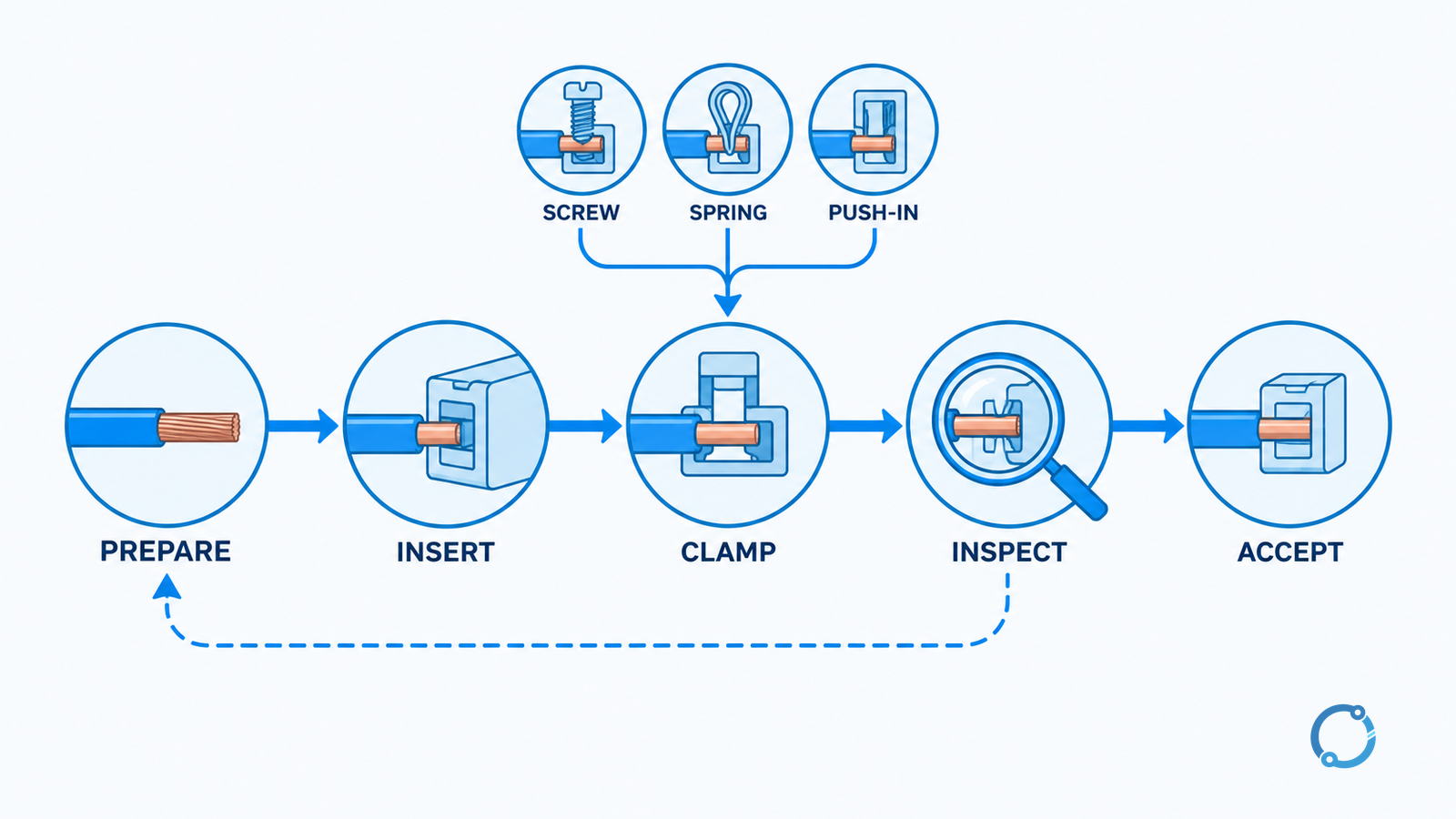
A verification-based selection procedure
- Write the conductor specification. Record material, solid or stranded construction, cross-section, ferrule requirement, strip length, and available bend space.
- Write the electrical duty. Record voltage, current, frequency or DC, fault environment, and the exact product-family standard.
- Write the installation environment. Record ambient, enclosure, pollution, vibration, maintenance access, and any required degree of protection.
- Shortlist by stated range. Remove any terminal that cannot accept the conductor or the voltage/current basis without an assumption.
- Compare the six dimensions. Fill the fixed table for every remaining candidate, using only the exact terminal’s data.
- Check the accessories. Confirm end stops, partition plates, jumpers, test access, marking, and DIN-rail space.
- Run a sample termination. Use the specified conductor, tool, and procedure; inspect the result without energizing the equipment.
- Record the acceptance basis. State which product data, instruction, and internal standard support the choice.
The result should name the conditions under which each shortlisted terminal is acceptable. It should not claim that one mechanism is universally faster, safer, or more reliable without the evidence to support that claim.
Acceptance and maintenance checklist
- Conductor material and construction are within the terminal’s stated range.
- The strip length and preparation match the terminal instructions.
- The conductor is fully seated and the clamp has engaged the conductive portion.
- The terminal, accessories, and marking are correct for the circuit and enclosure.
- The current, voltage, pollution, and ambient basis are recorded.
- The release tool and maintenance access are available.
- The joint can be isolated and verified before any adjustment.
- Re-termination uses a new or correctly re-prepared conductor end when required.
- The final assembly is checked against the panel drawing and the locally adopted requirements.
A terminal block is a small component with a large evidence burden. The right choice is the one whose complete connection system can be installed, inspected, and maintained under the actual conditions, not the one whose name sounds most modern.
Sources
- IEC 60947-7-1:2025, terminal blocks for copper conductors
- IEC 60947-1:2020, low-voltage switchgear and controlgear general rules
- IEC 60947-1:2020/COR2:2024, corrigendum
- UL 508A Supplement SA, specific component requirements
- 29 CFR 1910.303, electrical connections and installation requirements
The IEC and UL pages were used for public scope and document identity on 2026-10-23. The full standards are paywalled and were not accessed. The OSHA/eCFR citation is U.S.-specific. This comparison does not state a universal torque, temperature, vibration, cycle-life, or product-compliance conclusion; use the exact terminal-block data, installation instructions, and locally adopted requirements.