
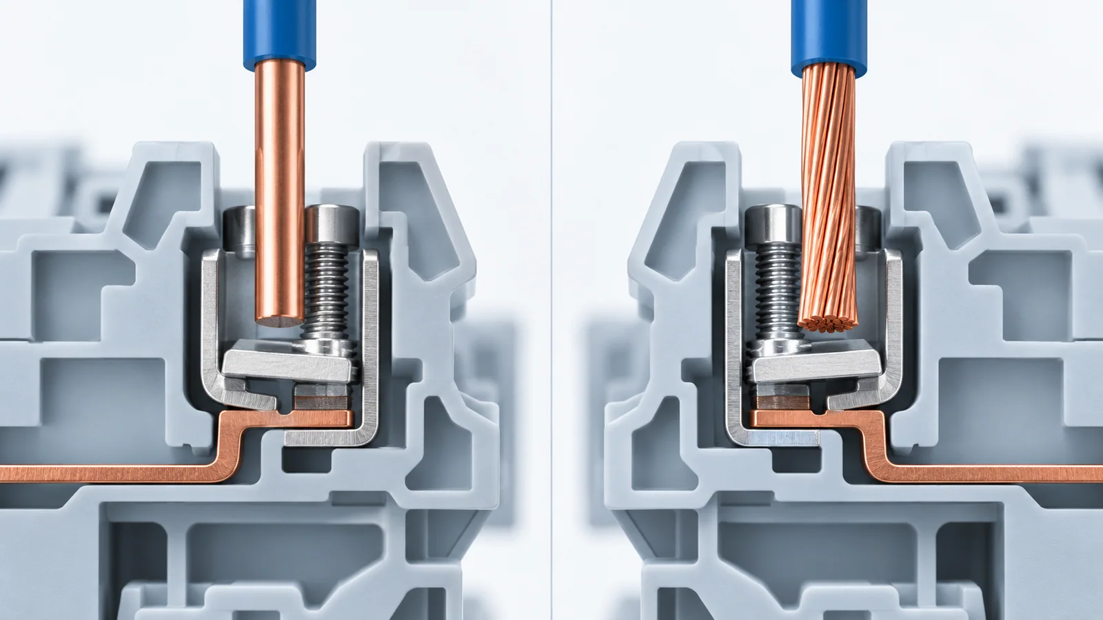
Use solid wire in a terminal block when the terminal explicitly accepts the conductor size and the installed wire will remain essentially static. Choose stranded or flexible wire when routing, repeated panel access or vibration makes bend endurance important—but match the conductor class and preparation to the terminal’s published acceptance data. Do not assume that bare strands, ferrules and crimp lugs are interchangeable termination methods.
The reliable choice is a system: conductor construction + terminal clamping unit + preparation + installation conditions. Neither solid nor stranded wire is universally superior.
Decision table
| Requirement | Solid conductor | Stranded conductor | Flexible fine-stranded conductor |
|---|---|---|---|
| compact, fixed point-to-point wiring | often suitable if listed in terminal data | suitable | may be unnecessary unless routing demands it |
| frequent bending during assembly/service | least tolerant | better | best of the three, subject to cable design |
| vibration or moving harness | generally less preferred | commonly preferred | often preferred with approved strain relief |
| insertion into a simple cage clamp | easy when straight and undamaged | needs controlled strands | may require a ferrule if the terminal instructions call for one |
| screw bearing directly on conductor | risk of scoring or extrusion | strands can spread or be damaged | usually requires the specified protection/preparation |
| field inspection | easy to see full insertion | inspect for stray/cut strands | inspect crimp/ferrule and full insertion |
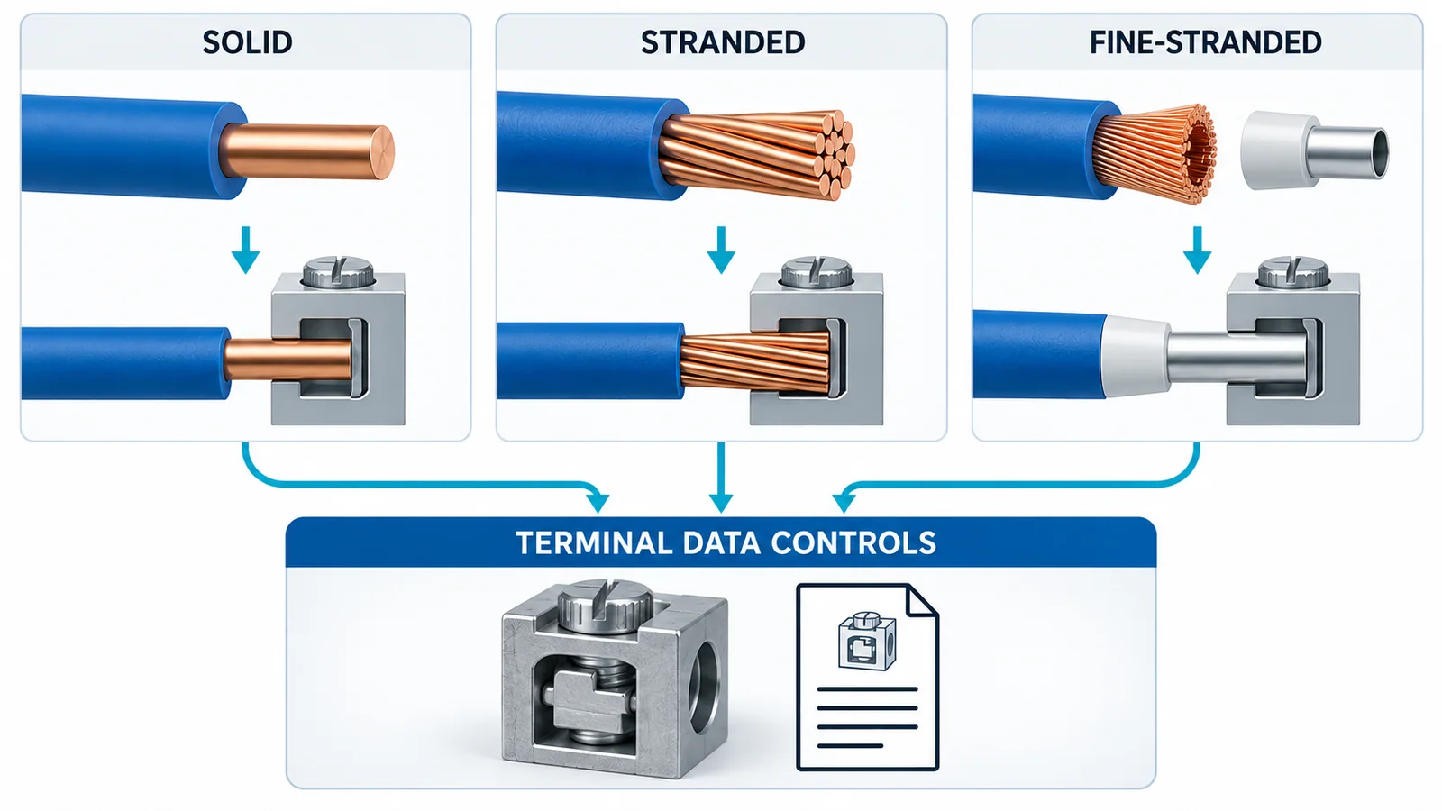
| termination rule | terminal data controls | terminal data controls | terminal data controls |
IEC 60228:2023 covers solid, stranded and flexible conductors in insulated power cables and cords. Conductor class describes construction and resistance requirements; it does not by itself prove that a particular terminal accepts that conductor.
What actually changes between solid and stranded wire
A solid conductor is one metallic element. A stranded conductor divides the same nominal cross-section among multiple wires; a flexible conductor uses more, finer strands. That construction changes:
- bend stiffness and fatigue behavior;
- how the conductor enters the clamping space;
- how pressure distributes under a screw, cage or spring;
- the likelihood of stray or cut strands;
- whether a ferrule or lug is part of the approved connection;
- minimum bend radius and strain-relief needs.
It does not justify a blanket claim that stranded wire carries more current. Ampacity depends on the complete cable, insulation, installation, ambient conditions, bundling and applicable wiring rules. Terminal temperature-rise performance also depends on the tested connection.
The terminal standard sets the product boundary
IEC 60947-7-1:2025 covers industrial terminal blocks with screw-type or screwless clamping units for specified copper-conductor ranges. IEC 60999-1:1999 addresses safety requirements for screw-type and screwless clamping units connecting rigid and flexible copper conductors within its scope.
These standards establish product requirements; they do not mean every conforming terminal accepts every conductor form. Check the exact terminal documentation for:
- solid, stranded and flexible conductor acceptance;
- minimum and maximum cross-section or AWG range;
- number of conductors per clamping point;
- copper-only or other conductor limitations;
- bare conductor, ferrule or lug options;
- strip length;
- tightening torque and tool;
- use of twin ferrules, jumpers or accessories;
- temperature and enclosure derating information.
For U.S. industrial control panels, recognized terminal-block component conditions and panel requirements must also be checked rather than inferred from an IEC marking. The UL terminal-block compliance guide explains that evidence path.
Match conductor construction to the clamping method
Screw clamp with a pressure plate or cage
A pressure plate or cage separates the screw tip from the conductor and can distribute force across the conductor bundle. Solid and stranded conductors may both be accepted. Fine strands still need controlled insertion and may require a specified ferrule.
Screw bearing directly on the conductor or lug
Direct screw pressure can score a solid conductor or displace strands. Some barrier strips are designed for ring or fork terminals instead of bare wire. Use the specified hardware stack and lug orientation; never add improvised washers or tin a conductor unless the product instructions explicitly permit it.
Spring-cage clamp
The spring maintains contact force without a torque setting. Stranded and flexible conductors are common, but the conductor must be fully inserted and the spring opened with the correct tool where required. Ferrule acceptance and cross-section range remain product-specific.
Push-in terminal
Rigid conductors and correctly crimped ferrules may push in directly, while flexible bare conductors may require the release tool. Do not force a fine-stranded conductor into a push-in opening; folded or displaced strands can create a partial connection.
When to use a ferrule
A ferrule consolidates fine strands into a controlled termination. It can improve insertion and inspection, but it also changes the connection geometry. Use one only when the terminal manufacturer permits it for the conductor size and ferrule type.
A defensible ferrule process includes:
- a ferrule sized to the conductor cross-section and insulation arrangement;
- a compatible crimp profile and calibrated/maintained tool;
- no missing, folded or protruding strands;
- complete conductor insertion into the ferrule barrel;
- crimp inspection and, when required, process testing;
- terminal cross-section/torque values applicable to ferruled conductors;
- no stacking of two conductors unless a twin ferrule and terminal are approved for it.
Solder-tinning fine strands is generally not a substitute for an approved ferrule. Solder can creep under sustained clamping pressure and alter the joint. Follow the equipment and terminal instructions.
Preparation workflow
Electrical work should be performed by qualified personnel under the site’s energy-control procedure. De-energize, isolate, lock/tag, verify absence of voltage and control stored energy before handling conductors.
1. Verify the design data
Confirm circuit voltage, current, conductor material/class/size, insulation temperature rating, short-circuit requirements, terminal part number, accessories and environmental conditions.
2. Cut and strip correctly
Use a cutter and stripping tool suitable for the conductor. Strip to the published length. Check that:
- the conductor is not nicked or scored;
- no strands were cut;
- insulation is not trapped in the clamping area;
- excessive bare conductor will not remain exposed;
- the conductor end is straight enough for full insertion.
If the stripped end is damaged, cut it off and prepare it again. Twisting strands aggressively can change the bundle shape and make insertion or ferrule crimping inconsistent.
3. Apply the approved preparation
Leave the conductor bare, fit the specified ferrule, or crimp the specified lug. Do not choose based on appearance. Record the crimp tooling where the quality plan requires traceability.
4. Insert to the stop
Keep the conductor aligned with the terminal. Confirm that all strands enter the clamping space and that insulation approaches the terminal without entering the electrical contact. For ring/fork lugs, preserve barriers and place the lug/hardware exactly as instructed.
5. Tighten or close the clamp
For screw terminals, use the manufacturer’s torque and specified tool. There is no universal torque for a wire size. For spring terminals, confirm the actuator returns to its service position.
6. Inspect and verify
Perform the approved visual and mechanical checks:
- no stray strands;
- no exposed copper beyond the permitted limit;
- correct terminal, conductor and marker;
- full insertion;
- correct ferrule/lug and crimp;
- correct torque record where required;
- conductor supported so the terminal does not carry harness strain;
- gentle pull check only when permitted by the procedure.
Common failure mechanisms
| Observation | Likely mechanism | Corrective action |
|---|---|---|
| loose strands outside clamp | poor preparation or insertion | de-energize, cut back and reterminate |
| conductor pulls out | wrong size/preparation, incomplete insertion or clamp not set | verify terminal data and remake connection |
| insulation under clamp | excessive insertion or wrong strip length | remake to specified strip length |
| heat discoloration | loose/high-resistance joint, overload or unsuitable component | remove from service under approved procedure and investigate the circuit |
| broken solid conductor near terminal | bend stress, vibration or inadequate support | revise routing/strain relief and conductor choice |
| ferrule deformed or partially inserted | wrong ferrule/crimp profile or terminal range | replace using an approved combination |
Thermal damage is a symptom, not a torque instruction. Do not simply tighten an energized or heat-damaged connection. Isolate it, identify the cause and replace affected components as required.
Selection checklist
Choose solid wire when all are true:
- the terminal accepts the exact solid conductor size;
- routing is fixed and bend demand is low;
- vibration and service movement are controlled;
- panel workmanship can preserve bend radius and support.
Choose stranded or flexible wire when its bend performance is needed and all are true:
- the terminal accepts the conductor class and size;
- the specified ferrule/lug or bare-strand method is available;
- routing and strain relief prevent terminal loading;
- the crimp/installation process can be inspected and controlled.
If the remaining question is whether a terminal block is the right connector family at all, use the separate terminal blocks versus wire connectors decision guide. For cable-end construction beyond panel terminals, see low-voltage cable termination fundamentals.