
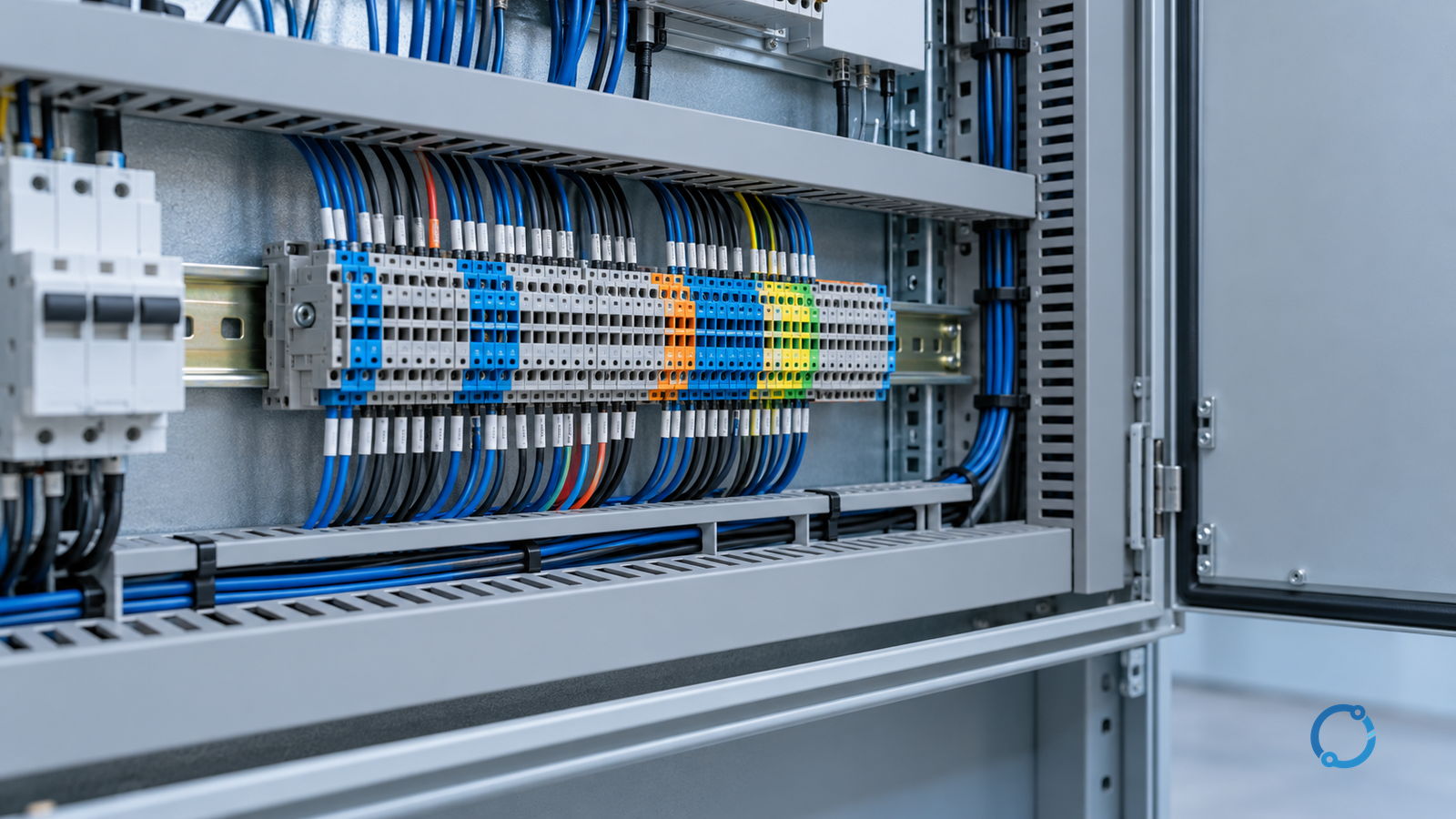
A serviceable terminal strip lets a qualified person identify the right circuit, reach its connection, work on it with the required isolation in place, and restore the correct configuration without disturbing adjacent wiring. Begin with the tasks the finished panel must support, then check the real terminal assembly, duct, conductor routes, labels and service tools together in the available enclosure space.
The output is an annotated layout and a checked terminal schedule—not simply a rail with enough nominal width for the blocks. This guide addresses industrial low-voltage panel planning. It does not replace the panel design, manufacturer’s instructions, risk assessment or locally applicable electrical requirements.
Start with the service task, not the rail length
Make a list of the work the panel owner is likely to authorize: identifying a field circuit, disconnecting an isolated conductor, replacing a damaged terminal, accessing a specified test point, or adding a documented spare circuit. Different terminal families need different release tools, access directions and accessory space. A strip that can be assembled on a bench may still be difficult to service after ducts and field cables are installed.
| Service question | What the layout must show | Hold for review when |
|---|---|---|
| Can the circuit be identified? | Readable device, strip, terminal and conductor references | Labels are hidden by ducts, wiring or covers |
| Can safe isolation be established? | Sources and interfaces identified in the documentation | External, control, backup or stored-energy sources are not identified |
| Can the connection be reached? | Front and side tool approach with adjacent wiring in place | A tool can reach only by moving unrelated conductors or defeating a guard |
| Can a conductor be handled? | Entry direction, bend area, duct exit and slack strategy | The specified wire cannot follow its allowed route without strain |
| Can the correct configuration be restored? | Terminal schedule, jumper positions and revision-controlled drawing | As-built arrangement or accessory identity is uncertain |
Safety boundary: design review is not permission to perform live work. Only qualified personnel should work under the site’s isolation, lockout, stored-energy and verification procedures, with the appropriate risk assessment and protective equipment. The U.S. OSHA safe-work rules apply within their jurisdiction; local rules and equipment instructions must also be checked. A terminal that remains energized from another panel or independent source must be identified and handled under the actual work plan.
Build the strip schedule before placing hardware
Start with current drawings, the interface list and the conductor schedule. Assign each required terminal a unique identifier and record its circuit function, source and destination, conductor size and material, connection technology, applicable voltage and current, accessories, and any protective-earth function. Mark the distinction between a planned spare terminal and a terminal whose purpose has not been resolved.
Include end plates, partitions, stops, markers, cross-connectors, test accessories and any special terminal widths in the physical model. Their fit depends on the exact product system; a shared rail profile or similar appearance does not prove accessory compatibility. The IEC 60947-7-1:2025 scope covers specified terminal blocks for copper conductors; it does not independently approve the complete panel layout or all conductor combinations.
The related mixed terminal block bill-of-materials guide explains how to move from circuit schedule to a kit. Keep the layout and that bill synchronized: a new partition or different terminal width can change both the physical strip and the order list.
Arrange for a clear sequence of work
Group connections so a technician can follow the documented circuit path without crossing unrelated wiring unnecessarily. The grouping should reflect the actual panel architecture and engineering rules: power, control, signal, protective conductors, external interfaces and other sources may need different treatment. Use barriers, separation distances, insulation and segregation only as justified by the applicable standards, equipment instructions and engineering assessment; there is no universal gap in this guide.
The power, control and signal separation guide addresses the reasons for segregation. Here the serviceability question is different: after those requirements are met, can each group still be identified and accessed? A barrier that satisfies an interface requirement but blocks the specified release tool needs a coordinated design solution, not an improvised removal during service.
Avoid relying on color alone to distinguish functions. Mark identifiers so that they can be read with ducts, installed conductors and required covers present. Match those identifiers to the drawing revision and terminal schedule. The IEC 60445 consolidated catalog entry covers terminal and conductor identification; the applicable adopted edition and detailed rules must be checked for the project.
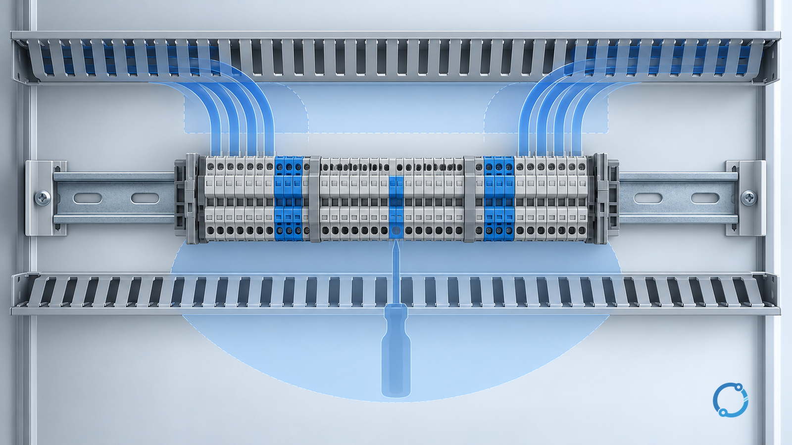
Check three-dimensional access with real components
A drawing’s top view can conceal the access problem. Check the full installed envelope: terminal height and depth, marker carriers, end stops, covers, duct height, conductor entry, cable bend and tool approach. Include the position of the door, neighboring equipment and any guard that must remain in place. Allow the actual terminal manufacturer’s specified conductor preparation and access arrangement.
Use a scale drawing, manufacturer data, a representative mock-up or another documented verification method suitable to the project. Test the planned service task, not just the theoretical reach to a screw head. For a spring terminal, for example, the release tool and the conductor may need access at the same time; a route that lets the tool reach but traps the wire does not prove serviceability. Never use a mock-up result to waive electrical clearances or product instructions.
Check the following separately:
- Tool path: the specified tool can engage in the correct direction without contacting unrelated parts or damaging insulation.
- Conductor path: the largest permitted or planned conductor can enter, bend and leave without exceeding its own limits or loading the connection.
- Duct interface: covers can be removed and replaced, and wires can be traced without pulling a large bundle loose.
- Accessory access: separators, test points, jumpers and end plates remain identifiable and accessible in the intended service state.
- Label view: the markings remain legible from the actual inspection position after wiring is installed.
The DIN-rail space calculation addresses the length of the assembly. Rail length is an input to the present access review, not its result. A wider enclosure or a different rail position may be needed even when all blocks mathematically fit.
Plan field wiring and change without weakening the design
Show where each field cable enters the enclosure, how it is supported, where its conductors turn into the duct and which terminals it reaches. The entry point, conductor bending characteristics, shielding treatment and mechanical restraint all affect the available service envelope. Do not assume the terminal itself provides strain relief for a cable; determine the system’s required support from the component and enclosure documentation.
When reserving spare positions, specify their function and boundaries in the schedule. A visually empty space is not necessarily electrically usable: future circuits may require separation, approved accessories, a different conductor size, thermal review or additional short-circuit assessment. Record the assumed future duty and require design review before the spare is used. If no future duty is known, identify the space as unassigned rather than claiming it is ready for any voltage or current.
The same caution applies to test and disconnect terminals. A test function must be coordinated with the actual circuit, permitted service procedure and protective scheme. The presence of a test point does not prove that measurement is safe or that a circuit can be opened without consequences.
Document the layout so it survives revision
The terminal schedule should link the strip identifier to the schematic, physical location, conductor identifiers, component family and approved accessories. Record which terminals are bridged, which are spare, and which sources may remain present when the local panel disconnect is open. Mark special maintenance constraints without treating a paper label as a substitute for isolation.
For each design change, compare the schematic, strip schedule, bill of materials and physical layout. If one changes, check the others. A replacement block with an apparently matching connection count may require a different end plate, marker, jumper or release tool. The terminal replacement checklist covers the separate compatibility decision.
The documentation also needs a way to capture as-built differences and the responsible design approval. An installer discovering that a duct blocks the tool should raise a layout issue rather than silently remove a separator, exceed a bend limit or substitute an unverified accessory.
Release the layout with a service-access review
Before approving the design, confirm:
- Every terminal has a traceable circuit function and a unique reference consistent with the controlled drawings.
- The complete product assembly, including accessories and end hardware, has been checked against the current component documentation.
- The planned conductors, bend paths, duct covers and tools fit together in three dimensions.
- Required separation, insulation, protective connections and barriers are preserved in both normal operation and the planned service condition.
- Labels and warnings remain visible, and independent sources and stored energy are identified in the work documentation.
- Spare capacity is documented with its assumptions, and use of that space requires a new engineering check.
- An unresolved access, clearance, rating or circuit-identity issue is returned to the responsible designer before release.
Where applicable in U.S. general industry, OSHA 1910.303 addresses equipment examination, wire-bending and connection space, and use of listed or labeled equipment in accordance with its instructions. Specific dimensions and requirements depend on the equipment, exposure and circumstances. This serviceability checklist adds a design-review method; it does not establish code compliance by itself.