
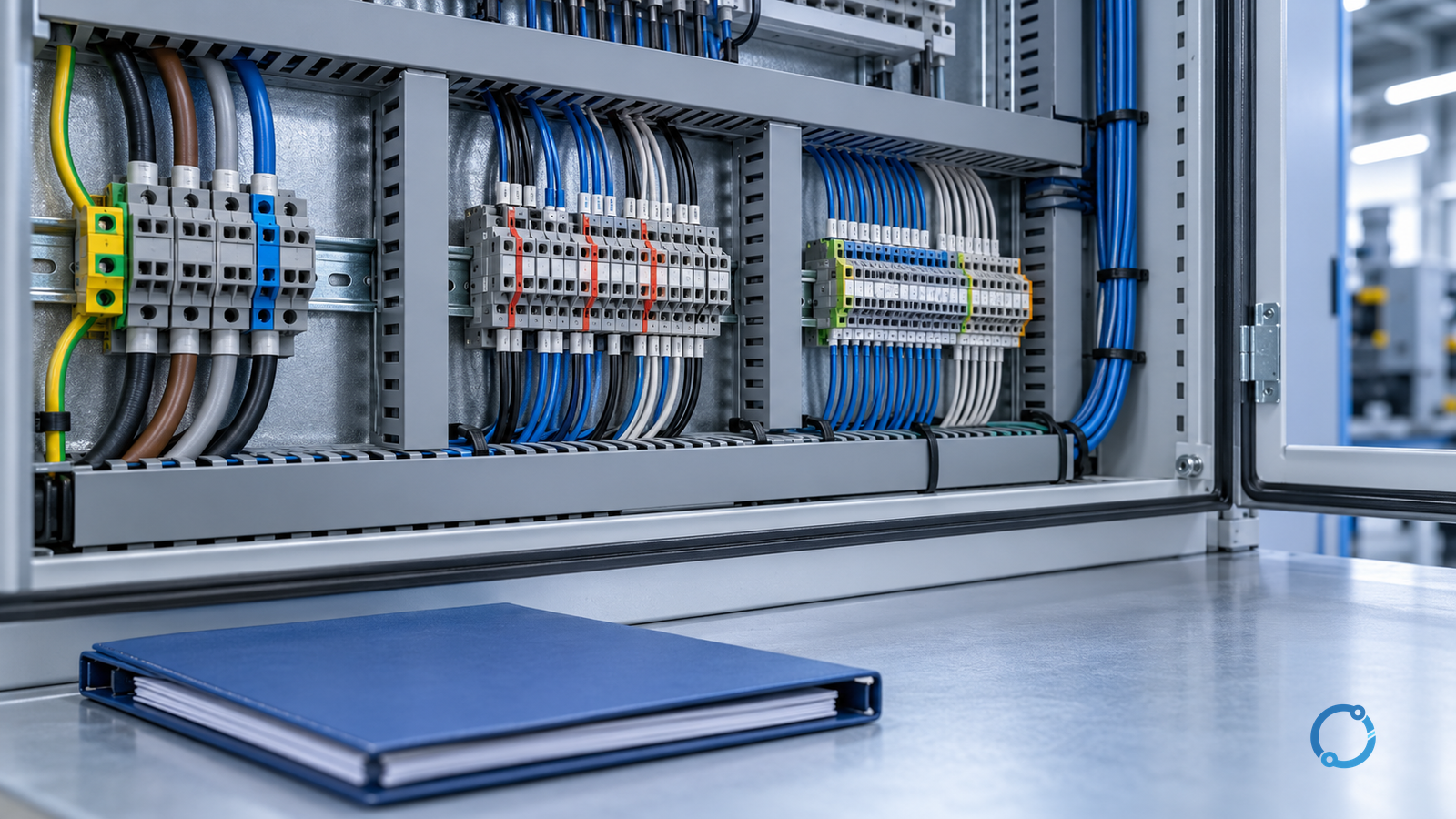
Separate terminal blocks by the hazards and dependencies of each circuit, not by the words printed above a DIN rail. A useful layout keeps power conductors away from sensitive signals, but it also has to control fault exposure, insulation distances, heat, arcing, conductor routing, electromagnetic coupling, testing access and maintenance error. Durable and safe terminal zoning continues beyond physical spacing to insulation, barriers, wiring practice, labels and as-built verification.
Start with one operating rule: a terminal belongs to a zone according to the highest credible electrical stress and failure effect that can reach it, not merely according to the nominal function in normal operation. A contactor-coil circuit may be called “control,” and a 4–20 mA loop may be called “signal,” but either can share a common, receive an induced surge, or carry a supply potential after a fault. That is why separation is a design decision.
This guide applies to industrial low-voltage panels and similar control assemblies. It does not prescribe universal spacing, segregation distances, wire colors, insulation values or equipment layouts. Those depend on the supply system, overvoltage category, pollution degree, altitude, product data, assembly standard and applicable local rules. Work near energized equipment must be performed by qualified persons under the site’s approved isolation, verification and work procedures. In the U.S. general-industry context, 29 CFR 1910.333 is one relevant work-practice reference; it does not replace the project’s electrical design standard.
What “separation” needs to accomplish
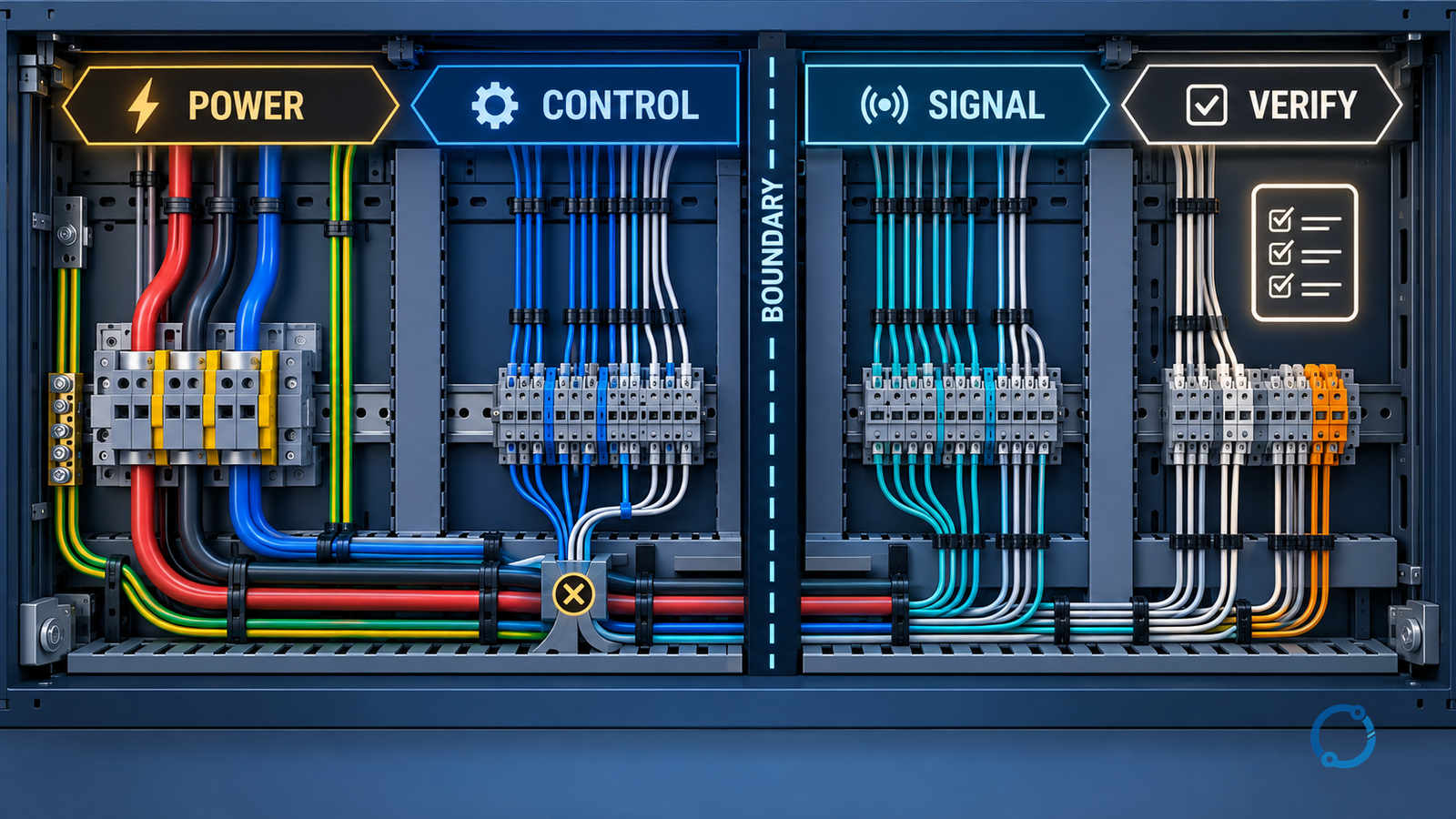
Three terminal groups are useful planning labels, but they should not become assumptions.
| Zone label | Typical functions | Main question that controls separation |
|---|---|---|
| Power | Incoming feeds, motor or heater circuits, transformer primaries, high-current distribution | Can a fault, arc, heat source or accidental contact affect another circuit? |
| Control | Relay and contactor coils, pilot devices, solenoids, starters and auxiliary supplies | Which supply potentials, switching transients and fault paths can enter the terminal group? |
| Signal | Sensors, analogue loops, digital communication, low-level feedback and instrument returns | Can electrical noise, common-mode voltage or an accidental power contact corrupt communication or create a hazard? |
An installation can have more than one power zone. A 690 V feeder and a 24 V DC power distribution are both “power,” yet they do not have the same insulation or fault consequences. Control may include 120 V AC and extra-low-voltage circuits. Signal may contain isolated contacts, shielded analogue pairs, communication buses and sensors with different reference points. The labels help navigation; they do not erase the engineering differences.
The layout therefore needs to state the purpose of each boundary. A physical gap can reduce accidental contact and cable coupling. A product barrier can support a more controlled separation between adjacent modules. A grounded metal partition can change an electric-field path, but it must be bonded and arranged according to the design rather than treated as a universal fix. Only an insulation system or isolating device can provide galvanic isolation; an air gap alone does not necessarily do so.
Define the terminal inventory before arranging the rail
Create the circuit schedule before choosing terminal-block hardware. For each circuit record:
- source and upstream protective device;
- nominal voltage, frequency and current;
- normal load and credible transient or inrush current;
- conductor material, cross-section and conductor class;
- every terminal that carries the circuit, including bridges and intermediate rails;
- signal type, reference and shield connection where applicable;
- expected fault current and protective-device response;
- overvoltage category or impulse-voltage duty required by the equipment design;
- pollution degree, altitude and any condensation or dust condition;
- enclosure, panel and terminal product data;
- whether the circuit is safety-related, measurement-related or ordinary operational control.
This inventory exposes dependencies that a drawing overview can hide. Two signal terminals may need to remain close to each other but be distant from a drive’s motor cable. A group of relay terminals may be electrically “control” while their flyback energy and switched inductive load require their own wire routing and suppression. An isolated RS-485 port may be functionally separated even when a nearby 24 V supply terminals sits on the same rail; the designer still has to show that the chosen arrangement preserves the isolation boundary.
The circuit schedule also determines whether a terminal is a field interface, an internal distribution point or a protective-conductor terminal. IEC 60947-7-1:2025 defines an international product-standard scope for industrial or similar terminal blocks for copper conductors. IEC 60947-7-2:2009 addresses protective-conductor terminal blocks, and IEC 60947-7-3:2009 addresses fused terminal blocks. Product family membership does not prove that a particular terminal is appropriate for the individual circuit; product ratings, accessories and assembly context still have to be checked.
Separate the different reasons for keeping circuits apart
A layout that passes one separation check can fail another. Treat at least six boundaries independently.
Electrical withstand and fault exposure
The assembly must withstand the voltages and transient stresses expected at each interface. Clearances and creepage distances are determined from the insulation coordination inputs, not copied from another panel. IEC 60664-1:2020+AMD1:2025 provides principles and requirements for insulation coordination in low-voltage equipment, while IEC 61439-1:2020 provides general rules for low-voltage assemblies. Those standards can tell the designer what has to be evaluated; they do not by themselves approve a site-specific layout.
The highest voltage present is not the only input. Transient overvoltage, pollution, altitude and the material group affect the required separation. A 24 V signal terminal close to a power terminal may appear electrically harmless in normal operation, but a loose conductor, a failed barrier or an accidental cross-connection can expose the signal circuit to a much greater potential. The physical arrangement should reduce that exposure and make the remaining reliance on insulation explicit.
Fire, arcing and mechanical damage
Power terminals can produce more heat and more energetic fault products than signal terminals. Locate high-current connections where conductors can be supported, inspected and serviced without leaning into signal wiring. Consider the direction in which a loosened conductor, a failed fuse or an arc product might move. Product barriers, separate ducts and terminal spacing may all contribute. No one measure substitutes for verified short-circuit coordination and assembly design.
For current and thermal selection, use terminal-block current rating versus actual load and terminal-block derating curves. These checks belong in the same record as the layout: a spacious zone does not correct a terminal that is unsuitable for the grouped thermal duty.
Electromagnetic coupling
“Put signals away from power” is a useful first move, but it is not a complete EMC solution. Coupling depends on the source and victim, separation, loop area, cable routing, shields, reference conductors, filters, switching rise time and enclosure bonding. Keep power and signal cables from sharing a path where the installation guidance requires separation. Route paired signal conductors together, establish the intended return and shield connection, and follow the drive or instrument manufacturer’s instructions for screening and filters.
Avoid treating a terminal marker as a shield. A terminal block can provide a convenient shield clamping point or a path to protective bonding only when the product and system design require it and when the impedance and connection method are appropriate. An extra ground connection can create a noise path as easily as it can solve one. For related panel architecture, see busbar versus terminal-block-and-cable wiring.
Heat and ventilation
Terminal resistance, grouping, enclosure temperature and adjacent heat sources all affect temperature rise. Keep heat-producing equipment and high-current terminals in locations with an approved cooling path. A signal terminal is especially vulnerable to measurement drift when a nearby power assembly creates a local temperature gradient. Physical separation can improve air movement, but it can also create unwanted bends or reduce the space available to route conductors.
The complete group of terminals, not just the visible block, determines the thermal result. Terminal blocks mounted next to each other may share heat through the rail and enclosure. The current in a bridge, conductor or return path may be different from what the drawing suggests. Validate the thermal arrangement against the actual product and assembly ratings; never use a nominal current on the nameplate to override a grouped thermal rating.
Testing and safe maintenance
The ability to isolate, test and replace a circuit without disturbing an adjacent one is part of separation. A fault in a power circuit should not require disconnecting important signal wiring merely to reach a protective device. A signal test point should not expose the technician to a power conductor through an unexpected path. Use physical grouping and clear labels, but also preserve the access required by the test procedure.
Documentation and human factors
A barrier that is removed for a field change and never reinstalled is not a permanent separation. The design should make the intended boundary obvious in drawings, labels and the bill of materials. Terminal designations must match the schematic, the wire markers, the field cable schedule and the terminal-block accessories. Use unique identifiers for left and right sides where necessary. A functional label such as “control” is not sufficient if two different supplies are present within the same group.
A seven-gate layout workflow
The following sequence keeps the layout from becoming a color-and-gap exercise.
Gate 1: confirm the safe state and design authority
Before inspecting existing wiring or changing a conductor, place the assembly in the safe state approved for the site. Isolate every source, including control supplies and back-feeds, verify absence of voltage with a functioning tester, allow stored energy to discharge, and secure the work area. Identify the person who owns the electrical design and the person who will inspect the completed change. A physical layout change can require drawing, labeling, vendor-data, protection-setting and validation updates.
Gate 2: define the zones from sources and failure paths
Mark the source of each circuit and every point from which an unexpected voltage can arrive. Include power supplies, back-up batteries, external communications, signal loops with remote power, inductive kickback and coupled circuits. Assign the circuit to the zone that controls its credible failure exposure. Then check whether isolation devices, barriers, separate ducts or product-specific partitions are needed.
Gate 3: verify the electrical separation inputs
For each boundary, state the maximum normal voltage, impulse-voltage basis, expected pollution degree, altitude and referenced insulation requirement. Confirm clearances, creepage distances and solid insulation from the applicable design method and product data. If a terminal block interrupts or supports a protective bond, check the specific protective-conductor requirement. If a fused terminal is used, verify the fuse, carrier and terminal compatibility rather than assuming that the assembly is interchangeable.
Gate 4: arrange conductors around the actual routes
Place power conductors so that they can be formed without touching sensitive signal wiring or obstructing service access. Keep signal pairs together and maintain the specified cancellation or return arrangement. Do not route a signal cable between two power conductors or through a wire bundle simply because a free terminal position exists. Where signals leave the enclosure, consider the separation, shielding, cable glands and field-side termination as part of the same route.
Gate 5: confirm thermal and mechanical grouping
Check conductor space, bending radii, terminal pitch, accessories, adjacent devices and ventilation. Verify the terminal’s current rating at the installed grouping and ambient condition. Confirm that barriers do not trap heat or prevent correct conductor insertion. Check that the assembled terminal row can accept the required wire range, ferrules, lugs and labels and remain serviceable.
Gate 6: expose and control cross-zone dependencies
List every intentional crossing: a switched control supply to a power device, a measurement voltage into a signal circuit, a communication port near a power supply or a protective conductor shared by several zones. For each crossing, identify the isolator, barrier, wire route, clearance and documentation that keeps the separation defined. Intentional crossings are acceptable when they are designed and verified; accidental crossings are not.
Gate 7: verify the as-built terminal system
Inspect the completed work with the schematic and the circuit schedule open. Confirm:
- every terminal designation is correct and unique;
- power, control and signal group boundaries are visible and uninterrupted;
- barriers, covers and accessories are installed as designed;
- conductor classes, ferrules and clamping methods match the approved build;
- signal shields and returns are connected as the system requires;
- protective-conductor connections and labels are intact;
- terminal torque or clamping is completed only with the product-specific instruction;
- thermal and current verification has been performed at a defined load;
- the drawing, BOM, label schedule and maintenance record reflect the as-built state.
If an inspection finding requires re-termination, use the correct conductor preparation and product instructions. The terminal-block replacement checklist and terminal-block markings guide help connect a replacement decision to the wider assembly rather than to appearance alone.
A practical zone map
The following conceptual sequence is useful for a new panel. It is not a dimensioned installation drawing.
- Start with incoming power and distribution terminals.
- Place protection and isolation equipment close to the power entry.
- Keep high-current outgoing conductors on a route with mechanical support and service access.
- Place control-supply and switched-load terminals next, with their own protection and markers.
- Place signal and communication interfaces away from high-current conductors and close to their cable entry where electrically appropriate.
- Provide the intended partitions, ducts, labels and test access between zones.
- Record every intentional crossing and every isolation boundary.
- Verify the assembled panel and update the documents.
The sequence is better than sorting terminals by the printed name alone because it follows the physical energy source, the protective device and the material current path. It also reveals when a “signal” circuit has an external power source or a “control” circuit has an incoming supply.
Common separation mistakes
Assuming that a gap is galvanic isolation
An air gap and a separate product may reduce coupling or contact risk, but galvanic isolation is supplied by a designed isolating component. State where the isolated interface is, its rated insulation and the reference it separates.
Using wire color as the only identifier
Color can assist with recognition, but colors differ between systems, installations and jurisdictions. Use terminal, conductor, circuit and cable designations that remain valid when a wire is replaced. Verify the marking convention from the project documentation.
Ignoring control supplies and coil transients
A control circuit is not automatically small, safe or noise-free. It may include inductive switching, back-EMF, high inrush current or a supply referenced to a power circuit. Keep flyback suppression, discharge and protective-device requirements in the control-circuit design.
Forgetting the common reference
Two signal circuits may be “signal” yet cannot be placed in one common group because they use different grounds or isolation references. A common terminal rail can also defeat an intended isolation barrier if the wrong terminal contacts the bracket. Review the bonding and commoning plan at the level of each circuit.
Changing the build without changing the drawing
Every added terminal, bridge, shield connection, barrier or cable route changes the as-built system. A functional check that passes once does not replace the updated drawing, labels and maintenance information. Future work depends on the panel telling the truth.
Verification before release
The release record should be proportional to the panel’s risk. For every separated group, it should show:
| Evidence item | What it proves | What it does not prove |
|---|---|---|
| Circuit schedule | The intended source, load, voltage and reference | That the installed wiring matches |
| Insulation-coordination inputs | The design basis for distances and dielectric checks | That every product or assembly detail was built correctly |
| Terminal and assembly data | The selected products and their permitted application | That a similar-looking replacement is interchangeable |
| Routing inspection | The deliberate physical separation and access | That signal quality or EMC performance is adequate |
| Continuity and bonding checks | The specified conductive paths are present | That the complete protection scheme coordinates |
| Functional and signal test | The intended control and measurement function operates | That no hidden fault path remains |
| Thermal and current record | The defined load was checked at the terminals | That all future operating conditions are safe |
| As-built documentation | The delivered panel is recorded accurately | That future modifications will follow the record |
Use the completed record to identify any open item. If a signal is noisy, a protective device trips, a terminal overheats or a barrier cannot be restored, stop the release rather than declaring the panel acceptable because the separation “looks right.”
What the layout cannot decide by itself
Terminal zoning cannot substitute for a short-circuit study, protective-device coordination, an insulation test plan, a hazardous-area assessment or an EMC design review. It cannot establish a product’s certification, prove that a control transformer has the correct fault capability or make a signal immune to a drive’s switching. It can, however, make the design assumptions visible and give the installer and maintainer a layout that supports the required electrical, thermal and functional boundaries.
The most useful separation is therefore not a decorative gap on a DIN rail. It is a documented arrangement in which every conductor can be traced to its source, every boundary has a purpose, every intentional crossing is controlled, and the completed panel can be inspected without relying on memory.
Sources
- IEC 60947-7-1:2025: Terminal blocks for copper conductors, published 2025, edition 4.
- IEC 60947-7-2:2009: Protective conductor terminal blocks for copper conductors, published 2009, edition 2.
- IEC 60947-7-3:2009: Fuse terminal blocks, published 2009, edition 2.
- IEC 61439-1:2020: Low-voltage switchgear and controlgear assemblies, published 2020, edition 3.
- IEC 60664-1:2020+AMD1:2025: Insulation coordination for equipment within low-voltage supply systems, consolidated edition published 2025.
- 29 CFR 1910.303: General electrical requirements, accessed 2026-10-29. This is a U.S. general-industry regulation, not a universal design rule.
- 29 CFR 1910.333: Selection and use of work practices, accessed 2026-10-29. This is a U.S. general-industry work-practice regulation, not a substitute for local standards.