
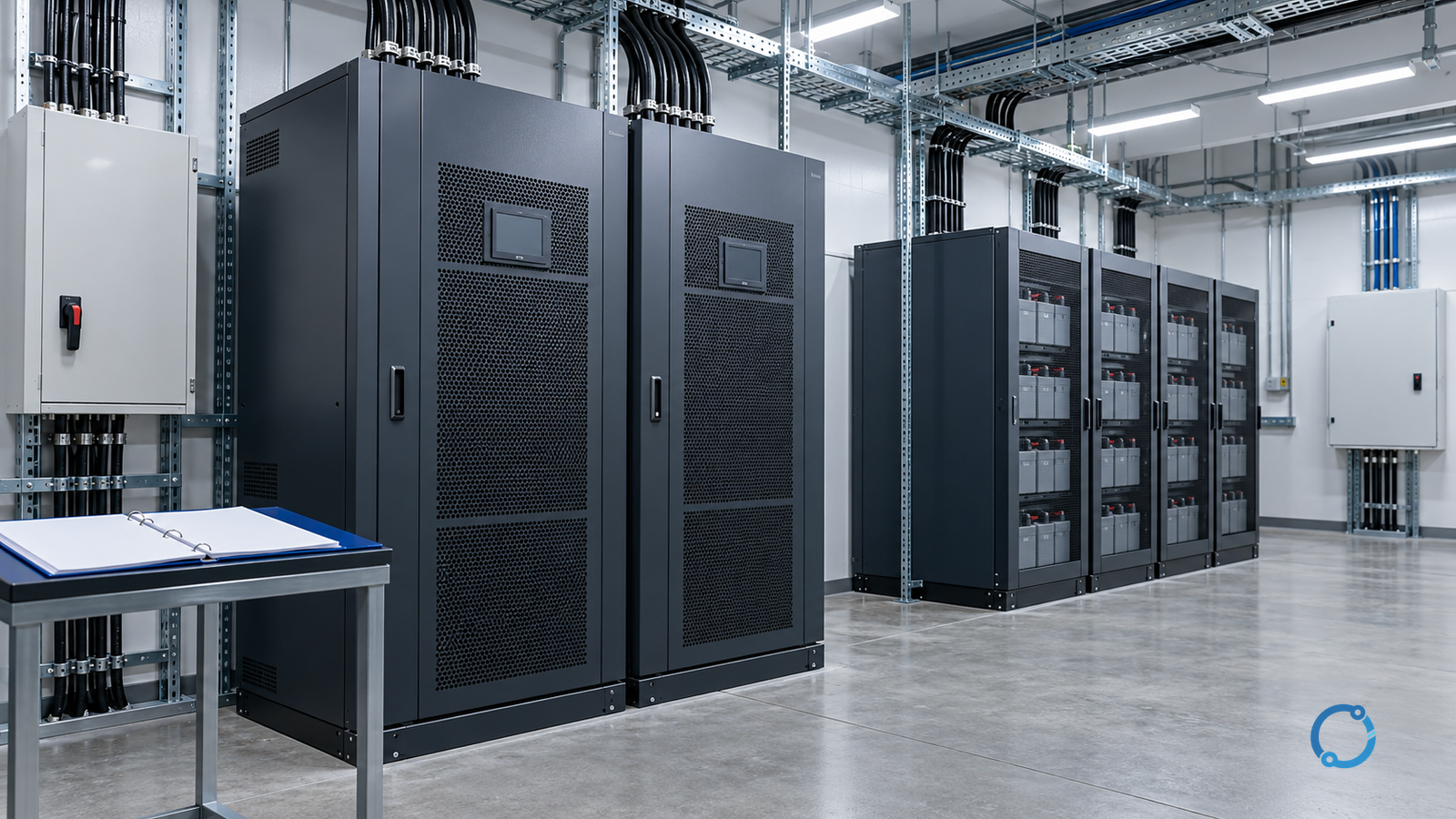
An uninterruptible power system is selected by the function that must remain available, not by a single kilovolt-ampere target. The protected equipment, duration of a process, allowable transfer disturbance, starting and non-linear currents, battery environment, redundancy expectation and maintenance plan all shape the solution. A UPS that is oversized in apparent power can still be wrong if its architecture defeats an upstream protective device, its battery cannot support the real load, or a maintenance bypass exposes a critical process to loss of power.
This guide sets out a transparent selection and verification workflow for low-voltage critical-power systems. It is written for data, communications, controls, laboratories, health-care support systems, industrial process controls and similar applications where a loss or disturbance has a defined operational consequence. It is not a universal design rule and does not prescribe a topology, battery duration, redundancy class or protection setting. Those decisions require the load owner’s requirements, equipment data, electrical design, fire and life-safety rules, local standards and a competent engineering review.
Work on UPS equipment and its battery system must be performed by qualified persons under the site’s approved isolation, stored-energy and verification procedure. A UPS can maintain hazardous voltage after its input is opened, and a battery string can deliver high fault current. Opening one upstream breaker does not prove that the output, bypass path, external battery or control supply is de-energized.
Define the critical function before selecting equipment
“Protect the whole room” is not a useful requirement until the protected function and allowed outage are known. Start with a short operating statement:
During loss of the normal source, the UPS must maintain [defined loads] for [defined condition], while preserving [data, process, communication or safety function], until [orderly shutdown, generator transfer, repair or other action] is complete.
The statement converts the project from shopping for a box into designing a service. It should identify:
- the process or business function supported;
- the consequences of complete loss, voltage sag, frequency change and transfer;
- the maximum acceptable interruption for each load;
- the time required for orderly shutdown or continued operation;
- the normal and abnormal source arrangements;
- who is responsible for operation and maintenance;
- the required reporting and alarm response;
- the conditions under which the load may be shed.
Classify loads by dependency rather than by room. A server, cooling unit, network switch, access-control device and environmental monitor may all be necessary, but they may have different tolerances and different durations. Troubleshooting voltage sags and swells is useful background because a requirement for sag ride-through is different from a requirement for a long backup period.
Build a load schedule from real operating states
A UPS must carry the connected load that is actually on its output at the worst credible moment. A spreadsheet copied from nameplates may overstate steady draw and understate inrush, non-linear current or coincident startup.
For each load record:
| Item | Evidence to obtain |
|---|---|
| Name and circuit | Exact equipment, location and UPS output group |
| Rated input | Voltage, frequency, phases, kVA and kW |
| Measured demand | Current and power at representative operating states |
| Power factor | Manufacturer data or appropriate measurement |
| Starting or inrush | Motor, compressor, transformer, charger or capacitive-load data |
| Harmonic or pulsed current | Manufacturer data, waveform evidence or input-current specification |
| Load criticality | Essential, essential with staged shedding, or nonessential |
| Allowed interruption | Zero-break, short transfer, orderly shutdown or no requirement |
| Runtime requirement | Time and end-of-discharge condition |
| Special environment | Heat, dust, corrosive atmosphere, vibration or altitude |
| Remote shutdown or signaling | Interface, polarity, protocol and failure state |
Calculate demand in both kW and kVA where applicable. The real-power requirement is the sum of active power, while apparent power must account for the vector sum of loads and power-factor effects. Do not simply add nameplate kVA values without considering diversity, actual load and the UPS input-current characteristics. A UPS vendor can evaluate a load list, but the owner remains responsible for stating the real operating case.
Review multiple states: normal full process, minimum load, staged start, motor acceleration, battery recharge, bypass operation and a fault in one load. The worst condition may not be the largest connected nameplate total. A small motor with a difficult start can dominate a transient, and a largely electronic load can stress the inverter or neutral path differently from a resistive load.
Decide what “availability” means for this project
Redundancy is not a substitute for a dependable source, adequate battery maintenance or a safe distribution design. It is a way to tolerate a defined failure while preserving a defined load. The requirement should say which failures are covered:
- one module failure inside a parallel UPS system;
- one independent UPS path failure;
- battery string or battery breaker failure;
- bypass-source failure;
- maintenance of one UPS while the load remains supported;
- failure of one cooling unit or control component;
- loss of the normal utility while a generator starts;
- a fault downstream of the UPS.
The designer then chooses an architecture and proves that the stated condition is actually covered. Two parallel UPS units with a shared single battery, a common output panel or a common bypass can leave a single point of failure. Likewise, a second power path is not useful if both paths share the same transformer, switchboard, cable route or control logic.
Avoid turning a label such as “N+1” into a promise. Define the module capacity, the load at the time of the failure, the grading of the units, the control behavior and the action required after a module is removed. A carefully specified modular UPS and a dual-bus architecture solve different problems.
Match the topology to the disturbance
A UPS can provide stored energy and conditioned output, but the topology determines what it does with sags, frequency variation, harmonics, overload, source loss and transfer events.
Double-conversion systems
A double-conversion UPS continuously rectifies the input and supplies the load through an inverter. That architecture can isolate the output from many input disturbances, subject to the product’s specified limits. It also introduces rectifier, inverter, battery-charging and cooling losses. The designer must verify input-current distortion, source capacity, battery recharge and bypass coordination.
Line-interactive systems
A line-interactive UPS commonly regulates voltage with a tap-changing arrangement and uses stored energy on source failure. It can be a good fit for some distributed loads, but its tolerance, transfer time and output behavior must match the load. Do not describe every line-interactive system as if it were double conversion.
Standby or off-line systems
A standby UPS may pass the normal source to the load and transfer to inverter output on a disturbance. The transfer gap and the waveform during battery operation are part of the selection. A load with a power supply that can tolerate a short break has a different requirement from an analogue process or an uninterruptible control function.
Parallel, modular and multi-bus arrangements
Parallel systems increase capacity or provide redundancy, but the control system must manage load sharing, module removal and output protection. A multi-bus design can provide separate distribution paths to dual-corded equipment. The design must verify that the two inputs are genuinely independent and that the equipment’s shared power-supply components do not become a hidden common failure.
The correct topology is the one whose verified behavior satisfies the operating statement, not the one with the longest feature list.
Establish runtime from an end condition
Runtime is meaningful only with a battery end condition, load profile, ambient temperature and allowance for battery aging. “Thirty minutes” at an unspecified load and temperature is not a procurement requirement.
Define:
- the complete UPS output load during battery operation;
- whether nonessential loads are shed immediately or after a delay;
- the minimum voltage or battery state at which the load must still operate;
- whether the purpose is ride-through to a generator, orderly shutdown or long-duration operation;
- the highest and lowest expected battery-room temperature;
- the replacement and capacity-test strategy;
- the required performance when one battery section is isolated for maintenance.
A generator can extend duration, but the transfer must occur within the UPS ride-through envelope and the generator must accept the UPS input and battery-recharge load. Substation battery charger sizing and substation DC supply redundancy provide useful contrast for stationary battery and direct-current systems; a UPS battery is integrated with a different set of converter, protection and load requirements.
Battery cycle count, float voltage, temperature compensation, ventilation and fire protection are design inputs. They cannot be reduced to a generic number without the battery manufacturer’s instructions and project standards. Keep battery management and failure detection visible in the selection, not hidden inside a maintenance contract.
Verify transfer, bypass and protective coordination
The UPS is part of a power system. Its input, output and bypass paths require coordination with upstream and downstream protection.
Check:
- prospective short-circuit current at each UPS terminal;
- rated short-time withstand and breaking capability of associated devices;
- input breaker selectivity with the normal source;
- output breaker selectivity with downstream distribution;
- bypass source capacity and fault level;
- ability to transfer to bypass without causing an unacceptable disturbance;
- reaction to an overload, inverter fault and battery isolation;
- isolation and lockout points for safe maintenance;
- neutral, bonding and earthing arrangement across all sources;
- reverse-power or back-feed protection where specified;
- generator and transformer interaction during rectifier startup.
Do not assume that a UPS prevents all downstream faults from reaching the source. Its internal semiconductor devices and bypass path have defined limits. The selected product, external protection and system fault study must be compatible.
Also test the less obvious failure commands. An emergency power-off, fire-alarm interface or remote shutdown must do what the site procedure requires without relying on an undocumented assumption. A clean data signal is not sufficient if the receiving control logic interprets its absence as a healthy state.
Treat input and output power quality as interfaces
The UPS has both a protected output and an input that affects the normal source. A large rectifier or battery charger can introduce harmonic current, notching or step loads. The generator, transformer and upstream protective devices must be sized for the actual UPS technology, filters and operating mode.
On the output, verify the stated steady-state voltage regulation, waveform, frequency behavior, overload capability, crest-factor capability and transient response against the load requirements. Do not compare a UPS’s output specification with a generic “pure sine wave” phrase. The product standard and test conditions explain what the number means.
The relevant IEC product framework includes:
- IEC 62040-1:2017+AMD1:2021+AMD2:2022 CSV, Safety requirements;
- IEC 62040-2:2016, Electromagnetic compatibility (EMC) requirements;
- IEC 62040-3:2021, Method of specifying performance and test requirements.
These standards provide product-dependent safety, EMC and performance frameworks. Product compliance does not prove that a particular installation has adequate runtime, selectivity, source capacity, earthing, ventilation or fire protection. Those are system-verification obligations.
Design the physical installation around service and stored energy
A UPS needs space for safe inspection, battery replacement, cable termination, ventilation and future maintenance. Clearance around equipment must follow the manufacturer’s instructions and the applicable installation rules. The battery area may need thermal control, spill or gas management, ventilation, fire detection or separation from incompatible equipment, depending on battery type and applicable standards.
Consider:
- floor loading and seismic restraint;
- cable entry, bend radius and access to terminals;
- cooling air inlet and outlet paths;
- dust, moisture and corrosion exposure;
- battery storage temperature and thermal runaway controls;
- isolation of battery voltage from maintenance personnel;
- external bypass controls and emergency shutdown locations;
- access for lifting equipment and future module replacement;
- labeling of all sources, including bypass, battery and external controls.
A UPS room that cannot be maintained safely is not truly available. The design should include the procedures, tools and isolation points required for a qualified team to perform routine and corrective work.
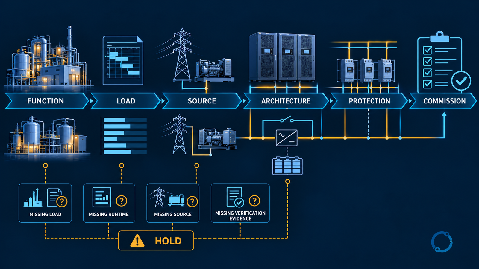
A nine-gate selection and verification workflow
The following sequence makes the requirements auditable and prevents a product brochure from becoming the design basis.
Gate 1: define the protected function and allowed outage
Write the operating statement. Identify the loads required for the function, the maximum acceptable break, the orderly shutdown time and the conditions that end the event. Obtain acceptance from the owner of the process, not only from the electrical installer.
Gate 2: inventory loads and operating states
Build the load schedule in kW and kVA. Include measured and nameplate evidence, starting current, power factor, harmonics, coincidence, diversity and future load only where an approved growth case exists. Mark which loads are automatically shed, manually shed or nonessential.
Gate 3: define the source and disturbance envelope
Record normal utility quality, available fault current, transformer and generator capacity, supply earthing, expected voltage and frequency excursions, and the time until an alternative source can accept load. Verify the UPS input limits against the actual source, including generator behavior during rectifier startup.
Gate 4: select and prove the architecture
Choose the topology and redundancy arrangement from the failure scenarios that must be covered. Identify every shared component: input source, bypass, output switchboard, battery, control, cooling, network and maintenance procedure. A redundant block without redundant dependencies is not automatic availability.
Gate 5: size output, input and batteries with transparent calculations
Check active and apparent power, UPS overload duration, inrush, battery recharge, source harmonic current and cable current. Calculate runtime from the selected battery data at the actual expected temperature and load. Record tolerances and design margin as explicit project decisions, not as hidden multipliers.
Gate 6: verify transfer, earthing and protection
Review all operating modes: normal, on-battery, bypass, internal fault, maintenance bypass and restart. Confirm neutral switching or solid-neutral behavior, bonding, fault-current paths, protective-device ratings and selectivity. Confirm that no source can back-feed a circuit expected to be isolated.
Gate 7: confirm environment and serviceability
Check ambient, ventilation, dust, altitude, floor loading, fire separation, battery ventilation and access. Confirm that the planned replacement path for batteries and modules is physically possible. Verify that isolation points and emergency controls are accessible and labelled.
Gate 8: integrate controls, alarms and operating procedures
Define which alarms are local, remote and safety-critical. Specify the required state after a communication failure. Include startup, staged load pickup, shutdown, bypass transfer, battery isolation and emergency response in the operating procedure. Assign someone to respond to each significant alarm.
Gate 9: commission and prove the delivered system
Commission with the manufacturer’s procedure and the approved project test plan. Verify input and output phase rotation, voltage, frequency, waveforms, battery voltage and polarity, alarm functions, transfer times as observable, protective-device operation, load sharing and battery runtime in a safe and controlled manner. Record the final settings and as-built configuration.
Commissioning must demonstrate the required behavior
A commissioning checklist that records only rated voltage and a successful start is incomplete. The test plan should trace back to the operating statement and identify which conditions were proved.
Typical evidence includes:
- approved drawings, product data and calculation sheets;
- insulation, continuity and earthing results where required;
- input and output measurements at defined loads;
- battery installation inspection and string measurements;
- alarm and remote-signal verification;
- transfer and return sequences under controlled conditions;
- load-bank or actual-load tests where the project requires them;
- protection and breaker coordination verification;
- cooling and ventilation performance;
- final parameter backup and access control;
- operator training and response records.
A runtime test must be planned with load, end voltage, battery temperature, safety controls and the authority to remove or isolate the load. Do not test a battery by creating an uncontrolled site outage. A product self-test, a short transfer check and a full sustained-runtime test answer different questions.
After commissioning, preserve an as-built record. UPS configuration settings often include battery type, string size, charge current, output voltage, transfer thresholds and remote interfaces. A firmware or board replacement can change behavior unless these settings are restored and verified.
Compare offers on equivalent evidence
Use the same evaluation matrix for each candidate. Do not compare a base UPS with an offer that excludes batteries, bypass equipment, input filters, monitoring cards, ventilation, installation or commissioning.
A useful comparison records:
| Criterion | Required value or condition | Evidence requested |
|---|---|---|
| Critical load | kW, kVA, power factor, inrush and operating states | Load schedule and calculation |
| Output sizing | Continuous and short-time capability | Product data and test basis |
| Runtime | Duration, load and end condition | Battery data and calculation |
| Architecture | Protected and unprotected failure points | Single-line diagram and module logic |
| Source compatibility | Input current, harmonics and generator interaction | Product data and system study |
| Transfer | Modes and load tolerance | Sequence description and test criteria |
| Protection | Fault level, breaker and selectivity data | Coordination evidence |
| Environment | Temperature, ventilation and footprint | Site data and installation plan |
| Service | Battery replacement, bypass and spares | Lifecycle and access plan |
| Controls | Alarms, protocols and cybersecurity | Interface specification |
| Verification | Factory, site and acceptance tests | Traceable test plan |
The lowest purchase price may conceal a shorter battery life, a maintenance bypass that requires a load outage or a module architecture that cannot isolate a failed section. The comparison must include the operating and support consequences.
Common UPS selection mistakes
Sizing only from the sum of nameplate kVA
Nameplate values may exceed real demand and omit coincidence or starting events. They may understate non-linear current and load power factor. Use measured operating states and documented equipment characteristics.
Setting runtime without defining end of discharge
A duration is not a complete performance requirement. State the load, battery temperature, end condition, aging strategy and what the operator must complete before energy runs out.
Calling shared infrastructure redundant
Two UPS units fed from one input, sharing one bypass or supplying one common fault path may not survive the scenario the owner intended to cover. Trace the entire path, including control and cooling.
Ignoring generator interaction
A generator can fail to accept the UPS input current, step load or battery recharge. Rectifier behavior and generator capacity must be assessed together before relying on the transfer sequence.
Treating a UPS as a fire, shock or fault-current solution
A UPS changes energy availability and may enlarge the arc-fault hazard. It does not remove the need for isolation, correct upstream protection, downstream selectivity, safe battery work or emergency procedures.
Leaving maintenance outside the design
If a battery cannot be replaced, a filter cannot be cleaned or a faulty module cannot be isolated without taking the load down, the expected availability has not been delivered.
Operating handover
At completion, the owner should be able to answer:
- Which loads are protected, and which are not?
- How long will the UPS support the present load?
- What action must occur before the battery reaches its end condition?
- What transfer modes exist, and what disturbance does each cause?
- Which alarms require an immediate response?
- How is one module, battery section or source isolated safely?
- What additional failure is not covered by the chosen redundancy?
- When and how will battery capacity, cooling and protective functions be checked?
- Who has authority to shed load, shut down the UPS or transfer to maintenance bypass?
If these questions do not have documented answers, the system is not fully commissioned even if the output voltage looks normal.
The selection rule
Select a critical-power UPS by connecting the protected function to a verified electrical and physical system. Define the load and duration, source and disturbance envelope, availability requirement and maintenance strategy. Prove the topology, fault coordination, battery basis and environmental installation. Then commission against those requirements and preserve the evidence.
The best UPS for a critical application is not simply the largest unit or the one with the shortest claimed transfer time. It is the system whose actual load, source, battery, bypass, protection and service arrangements have been demonstrated to support the required operating statement.
Sources
- IEC 62040-1:2017+AMD1:2021+AMD2:2022 CSV: Uninterruptible power systems (UPS) – Part 1: Safety requirements, consolidated version incorporating both amendments.
- IEC 62040-2:2016: Uninterruptible power systems (UPS) – Part 2: Electromagnetic compatibility (EMC) requirements; the linked redline edition includes the official standard and comparison with the prior edition.
- IEC 62040-3:2021: Uninterruptible power systems (UPS) – Part 3: Method of specifying the performance and test requirements, third edition.
- 29 CFR 1910.333: Selection and use of work practices, accessed 2026-10-29. This is a U.S. general-industry work-practice regulation; the project must use the applicable local safety and electrical requirements.