
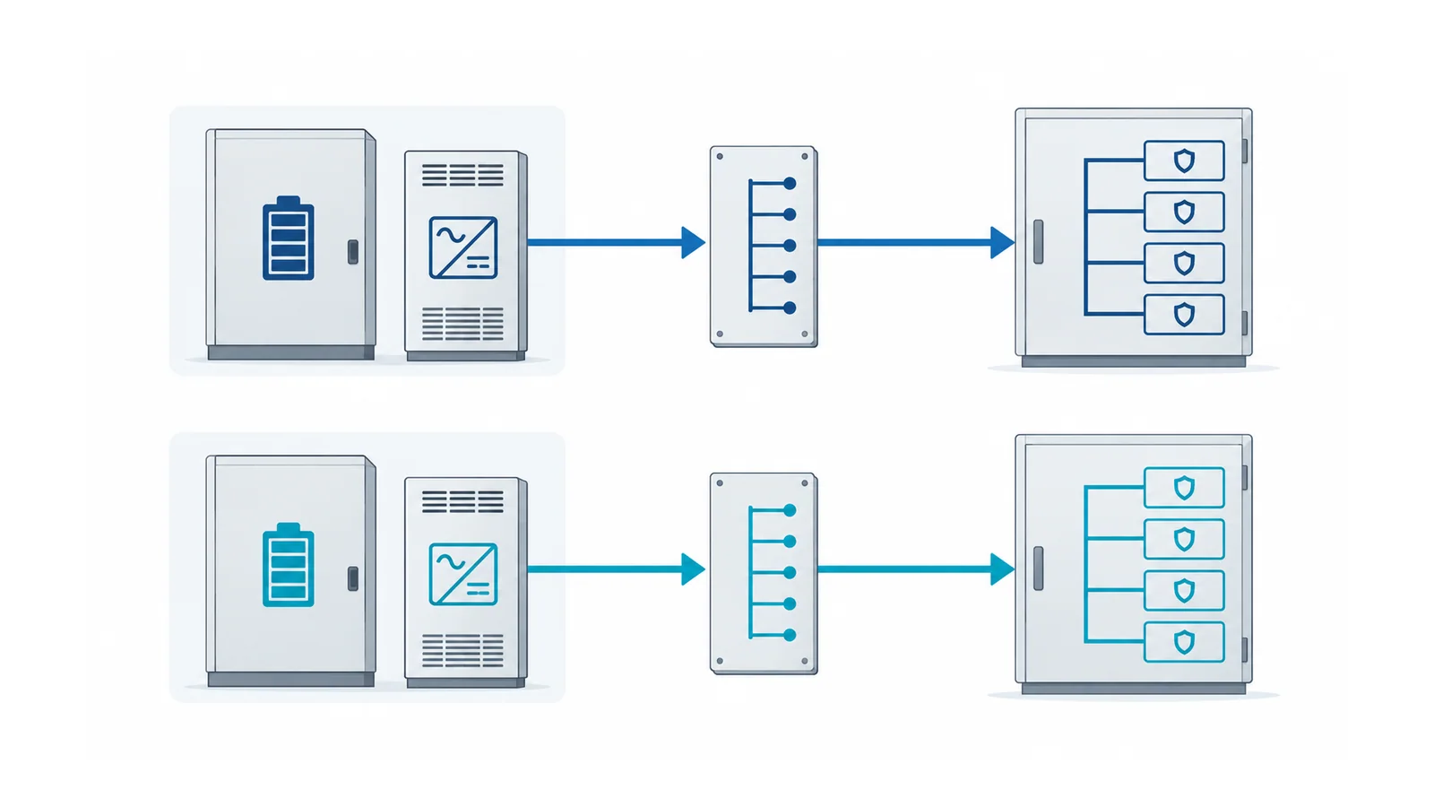
Select a substation DC supply scheme by asking which protection functions survive each credible failure, not by counting chargers or drawing two outgoing feeders. Two chargers connected to one battery and one bus improve some charger-availability cases; they do not create two independent stored-energy sources or remove a common bus fault.
The useful output is a failure-survival record covering normal operation, loss of alternating-current (AC) supply or charger, battery unavailability, distribution faults and planned maintenance. It must identify what remains able to detect and clear a power-system fault, for how long, and under which documented limits.
This review concerns battery-backed stationary DC systems for substation control and protection. It is an architecture comparison, not a battery/charger sizing method, a live switching procedure or a universal requirement to install two complete systems.
Define independence before comparing schemes
List the required functions, not just the loads: main and backup protection, breaker tripping, breaker-failure actions, communications needed by protection, control and necessary alarm delivery. Separate loads that must remain available from loads that may be shed under the station’s accepted philosophy.
The distribution-substation overview places these functions in the wider power path. Here, draw the auxiliary supply separately from the AC single-line diagram. A station can lose its ability to clear the next fault even while its main AC equipment remains energized.
Mark the boundaries of proposed systems A and B. Trace batteries, chargers, AC inputs, DC buses, protective devices, outgoing feeders and shared returns. Also identify physical dependencies such as common rooms, cable routes, panels and maintenance access. Define the failure cases against which separation is required.
The public scope of IEEE 946-2020 addresses stationary DC system design, including lead-acid and nickel-cadmium batteries, static chargers and distribution equipment, with guidance on ratings, interconnections, instrumentation and protection. It is relevant to substations, but its scope page is not a mandate for one topology or a completed project design.
Compare four architectures against explicit failures
The table assumes conventional battery-backed arrangements and properly designed outgoing-circuit protection. It is a conceptual comparison, not a guarantee that a real scheme achieves selective clearing or the required autonomy.
| Architecture | One charger or its AC input unavailable | Battery path unavailable | Main DC bus fault | Maintenance implication |
|---|---|---|---|---|
| One battery, one charger, one bus | Battery can support the accepted duty until its limit | Stored-energy backup is lost; charger-only operation needs separate proof | Common supply can be lost | Source maintenance needs an accepted temporary state or planned loss of functions |
| One battery, two chargers, one bus | Surviving charger may maintain service if its capacity and AC dependency permit | Still one shared battery path | Still one shared bus | Charger maintenance improves; battery and bus maintenance remain common constraints |
| One battery with separated distribution paths | Depends on the charger arrangement; outgoing-path duplication does not decide it | Shared battery remains a common dependency | Depends on where the fault lies and how branches are isolated | Distribution maintenance may improve, but shared-source work remains constrained |
| Two battery/charger/bus systems with separated required paths | Other system can support its assigned functions; review any shared AC dependency | Other system can retain its assigned stored-energy duty | Other bus can survive if interconnections do not propagate the fault | More possible maintenance states, with additional equipment and restoration complexity |
“Can survive” always means for the documented duty and operating state. A diagram containing two sources does not establish the minimum terminal voltage, fault coordination or independence of every connected function.
The IEEE PSRC report on redundancy in protective relaying, especially its battery and physical-separation discussion, distinguishes duplicated circuits supplied by one battery from more fully separated systems. It also discusses monitoring and application constraints. Treat it as engineering guidance, not a universal regulatory obligation.
Trace the power and protection paths together
For each critical function, record both the DC supply to the protective device and the DC supply to the actuator. An energized trip coil is not useful if its initiating relay has lost power. A surviving relay is not enough if the trip path or breaker mechanism is unavailable.
Keep coil voltage and command-path verification in the substation trip-circuit design checklist. The station-wide review must supply that checklist with the correct worst-case source voltage and available path for each operating state. Nominal DC voltage is not the answer at the coil terminals.
A useful function record contains:
| Field | Question it must answer |
|---|---|
| Required function | What fault or operating condition needs detection and clearing? |
| Normal source and path | Which battery, charger, bus and feeder support it? |
| Credible failure | What single event or accepted combination is being reviewed? |
| Surviving function and path | What still detects and acts, rather than merely indicating availability? |
| Time and voltage basis | Can the surviving supply support the required duty within equipment limits? |
| Alarm and response | How is the degraded state detected and who can restore or restrict operation? |
| Maintenance/restoration evidence | How will the accepted state be demonstrated and returned to normal? |
Do not label a row “redundant” while leaving the surviving actuator path blank.
Account for both battery and charger fault contributions
The DC distribution study needs fault contributions and circuit impedances for the actual operating configurations. Batteries and chargers do not behave like a single ideal AC source. Charger technology, current limitation and protective behavior can matter alongside the battery’s contribution.
NRC NUREG/CR-7229 reports battery/charger fault testing in a nuclear-plant context. Its abstract identifies charger contribution and DC circuit impedance as factors when establishing protective-device settings. That is evidence for including these inputs, not permission to reuse a nuclear plant’s values or coordination rules in another station.
Evaluate downstream feeder faults and bus faults separately. A downstream device that clears a branch selectively may preserve the bus. A fault at a shared upstream node can defeat that expectation. Verify DC interrupting capability, polarity restrictions where relevant, and the coordination evidence for each device and source state. Do not apply an AC interrupting rating to a DC application by assumption.
Also distinguish loss of supply from an earth-fault indication. In an intentionally unearthed DC arrangement, the behavior of a first earth fault and subsequent faults depends on circuit design, monitoring and fault location. Do not modify grounding or connect system returns together to silence an alarm. The accepted earthing and monitoring philosophy belongs in the system study.
A bus tie is an operating state, not free redundancy
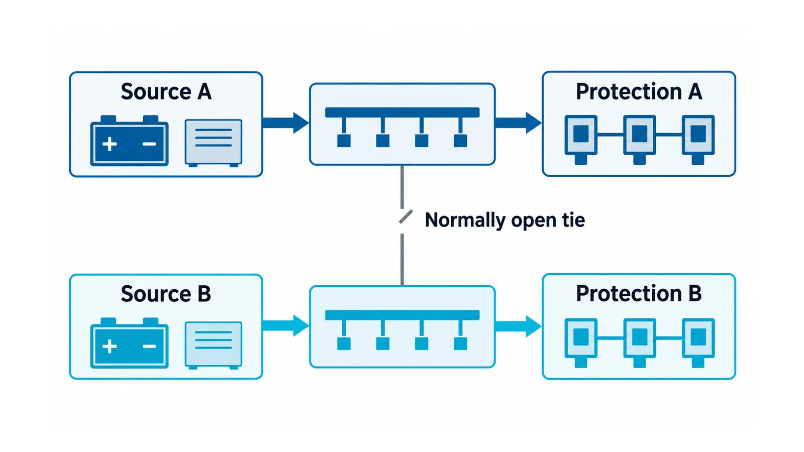
A normally open tie can help with a planned supply transfer, but closing it changes fault propagation, source contribution and possibly earthing/monitoring behavior. Record whether any chargers or batteries become paralleled, the permitted voltage difference, equipment suitability, isolation arrangement and protection response. Obtain those limits from the actual design and equipment, not a generic switching sequence.
If the tie is closed during maintenance, ask whether a bus fault that was contained in normal operation can now affect both protection groups. An automatic transfer also needs a defined trigger, transfer behavior, failed-transfer response and alarm. Do not assume that a “healthy alternative supply” indication proves the alternative path can deliver the trip duty.
Physical separation and operating discipline should match the credited independence. A common cable tray, panel terminal, flood exposure or maintenance action may remain a shared failure despite two batteries. Document the residual dependency; either accept it under the station’s reliability objective or redesign it.
Example: normal, degraded and maintenance states
Consider a hypothetical station with protection groups A and B, each assigned to a separate battery/charger/bus path, and a normally open tie. The objective is to preserve the specified fault-clearing function after one DC source-path failure. This is a teaching example, not a rule for every substation.
Normal state: trace both protection groups through their required breaker actions. Check for shared relay supplies, communications power, returns and trip-path components. Separate source labels do not settle those questions.
Battery A unavailable: identify the exact surviving B functions. Verify the B duty, terminal-voltage range, detection and clearing times, and alarm response. If the needed breaker action still depends on A, the architecture fails the stated objective even though B’s bus remains healthy.
A-side maintenance with the tie closed: reassess fault containment and the credited source independence. If a common supply now supports both groups, record the temporary reduction and the required operational restrictions. Do not continue to describe the maintenance state as fully independent A/B protection.
Acceptance requires evidence for all three states, not a successful normal-state trip alone. The breaker-trip troubleshooting guide also explains why a trip command, coil operation and breaker opening are separate observations.
Release the architecture with its limits visible
Retain the source/distribution diagram, critical-function register, load/duty and voltage studies, fault-coordination evidence, alarm matrix and accepted maintenance states. Define review triggers for added loads, replacement chargers or batteries, new communications dependencies and changed tie operation.
Tests or transfers can remove protection or trip energized equipment. Only authorized, qualified personnel should perform approved work under station switching, isolation, test and restoration procedures. For applicable U.S. general-industry electrical work, OSHA 1910.333 sets de-energization and safe-work boundaries; determine the rules that actually govern the facility.
Choose a simpler scheme when its documented surviving functions and response arrangements satisfy the accepted requirement. Choose greater separation when a shared dependency defeats a necessary protection outcome. In either case, the decision must name the failures it covers and the ones it does not.