
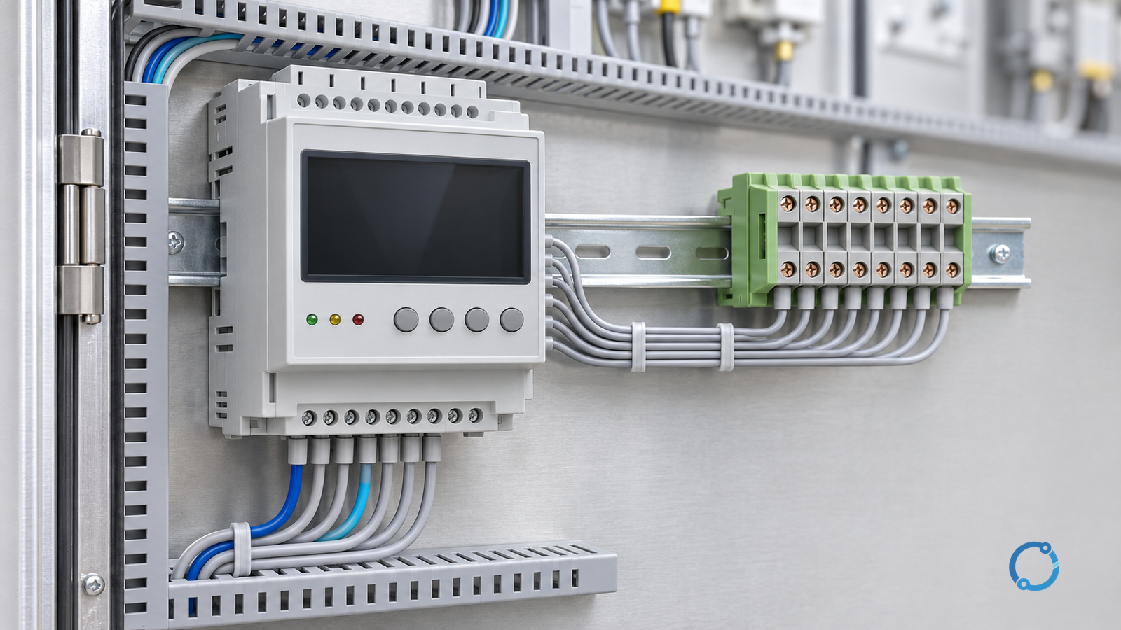
A protective relay turns a measured system condition into a trip decision. The generic chain is:
measurement -> comparison or characteristic -> time decision -> trip output
That chain is more useful than memorizing a list of relay types. A definite-time overcurrent relay, an inverse-time overcurrent relay, and a differential relay all perform the chain, but they measure different quantities and use different decision rules. The relay is also only one part of a protection system. Current or voltage transformers, the DC supply, the trip circuit, the breaker mechanism, and the test record all affect whether a fault is cleared.
This explainer builds the chain from the measurement boundary outward. It compares three common operating principles and stops before setting calculations, coordination studies, and scheme-specific commissioning. Those tasks require the fault study, equipment ratings, approved protection philosophy, and relay documentation.
Measurement comes before logic
A relay cannot decide correctly if its input is wrong. Current transformers (CTs) and voltage transformers (VTs) scale system quantities to levels the relay can measure. Their ratio, polarity, burden, connection, and secondary wiring define what the relay actually sees.
For an overcurrent function, the relay may measure phase current, residual current, or another derived quantity. For a distance function, it may combine voltage and current to estimate impedance. For a differential function, it compares currents from several locations around a protected zone. The measurement labels matter because the same numerical value can mean different things in different schemes.
The relay’s measurement also has a time window. A fault current may contain a DC offset, harmonics, or a changing magnitude during the first cycles. A digital relay uses filtering and an algorithm to estimate the operating quantity. The protection engineer must understand the declared measurement range and the effect of CT saturation, VT fuse failure, or abnormal system conditions. A display that shows a current does not prove that the current is suitable for every protection function.
IEC 60947-1:2020 is an official general-rules publication for low-voltage switchgear and controlgear. Its IEC listing is useful for equipment-family orientation, but the protection function, measurement transformers, and settings must be verified from the actual relay documentation and the approved protection study.
The common decision chain
Most protection logic can be described in four blocks:
- Acquire the measured quantity or quantities.
- Compare the result with a threshold, characteristic, restraint rule, or zone boundary.
- Apply a time criterion or additional supervision.
- Assert a trip output when the complete logic is satisfied.
The blocks may be implemented in electromechanical, static, or digital hardware. The implementation affects testing and diagnostics, not the basic engineering question. The relay must be able to distinguish the intended fault condition from load, inrush, motor starting, switching transients, and other non-fault events within its design scope.
Definite-time logic
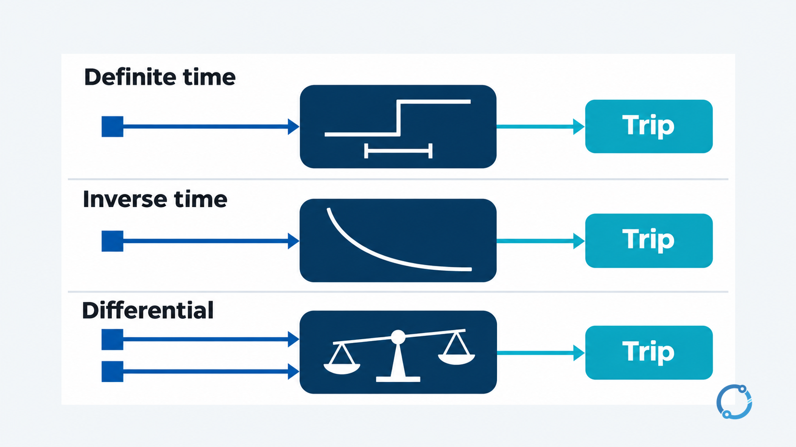
Definite-time protection uses a selected operating quantity and a threshold. Once the quantity exceeds the threshold and the function is enabled, the relay starts a time delay. If the condition remains present for the set delay, the relay trips. The delay is intended to be independent of how far the current is above the threshold, although the relay’s declared characteristics and filtering may introduce practical limits.
The logic is easy to describe:
If measured current is above the pickup for longer than the delay, trip.
That simplicity is useful when the protection engineer wants a clear time boundary between downstream and upstream devices. It is also useful when the fault level is expected to be high and a fast, predictable operation is required. The relay may have instantaneous elements, definite-time elements, or both.
The phrase “definite time” does not mean “no settings.” The pickup, delay, reset behavior, measurement filtering, and optional directional or voltage supervision all belong to the scheme. A universal pickup or delay would be unsafe because the correct values depend on the system voltage, equipment rating, fault levels, coordination, and the protection philosophy.
Inverse-time logic
Inverse-time protection also starts with a measured quantity, but the operating time changes with the magnitude of that quantity. A simplified overcurrent relationship can be written as:
operating time = function of current magnitude
As the current rises above the pickup, the time to trip generally becomes shorter. The exact curve, time multiplier, reset characteristic, and applicable current range are defined by the relay and the selected protection standard or setting. Digital relays may offer several curve families and additional logic.
Inverse-time protection is useful where the protection engineer needs a time-graded response across a network with changing fault levels. The shape of the curve can help coordinate devices that see different current contributions for the same fault. It does not eliminate the need for a coordination study. The curve must be checked against the upstream and downstream devices, the equipment damage curve, the CT performance, and the minimum and maximum fault levels.
The article does not provide a universal curve or time multiplier. The OHELE overcurrent relay coordination worked example shows the kind of study inputs that belong outside this operating-principle explanation.
Differential logic
Differential protection compares currents that enter and leave a defined protected zone. In a simple two-terminal zone, the currents should balance during healthy through-load operation. When a fault occurs inside the zone, the current entering and leaving no longer balance. The difference is the differential current.
The basic concept can be expressed as:
differential current = current entering the zone – current leaving the zone
Real schemes include restraint, ratio matching, phase compensation, CT error, saturation, and other security features. A relay may use a percentage differential characteristic, a high-set instantaneous element, or additional logic. The exact slope and settings are scheme-specific and require the protected equipment data and fault study.
The physical principle explains why differential protection can be selective: it responds to a fault inside its zone while remaining stable for through-faults outside the zone, provided the current transformers and settings are correct. That selectivity is not automatic. A CT ratio error, reversed polarity, wiring error, or saturation can create false differential current. The OHELE transformer differential relay settings guide covers the additional complexity of transformer applications.
A comparison of the three principles
| Principle | Primary evidence | Decision rule | Useful boundary |
|---|---|---|---|
| Definite-time overcurrent | Current magnitude | Threshold plus fixed delay | Clear time separation and predictable operation |
| Inverse-time overcurrent | Current magnitude over time | Threshold plus a magnitude-dependent characteristic | Coordination across changing fault levels |
| Differential | Current balance around a zone | Difference after restraint and matching rules | Selective protection of a defined zone |
The table is not a ranking. A differential scheme is not automatically better than an overcurrent scheme for every application, and an inverse-time curve is not automatically more sophisticated than a definite-time element. The protection engineer selects the principle that matches the protected equipment, the fault types, the system topology, the available measurements, and the required speed and selectivity.
Distance protection provides another example. It uses voltage and current to estimate the impedance to a fault and applies zone boundaries. The OHELE distance protection calculation guide explains that separate measurement basis. It belongs in the same family of protection logic but is not a synonym for overcurrent or differential protection.
The trip output is not the whole system
When the relay asserts a trip output, the signal must reach the breaker trip coil through the trip circuit. The DC supply must be healthy, the trip contacts must be closed, the wiring must be intact, and the breaker mechanism must be capable of opening. A relay that measures and decides correctly but cannot deliver trip energy does not clear the fault.
Protection systems also need:
- instrument-transformer test facilities;
- trip-circuit monitoring;
- auxiliary-supply monitoring;
- breaker failure or backup protection where required;
- lockout and reset logic;
- event recording and time synchronization;
- isolation and safe test points; and
- documented functional testing.
The OHELE lockout relay design guide explains the difference between a trip command and a lockout state. The substation trip-circuit design guide covers the DC path that delivers the command. Those pages are relevant precisely because a relay’s operating principle is only one layer of the protection architecture.
Testing the logic, not just the display
A commissioning test should prove the complete function:
- Confirm the relay configuration and firmware reference against the approved file.
- Verify CT and VT ratio, polarity, phase assignment, and secondary wiring.
- Inject or simulate the measured quantity at the relay terminals where the procedure permits.
- Verify pickup, reset, timing, restraint, and output mapping as applicable.
- Confirm the trip output operates the correct trip circuit and breaker.
- Check targets, event records, alarms, and communication status.
- Restore test links and record the final as-left condition.
Injection at the relay terminals does not prove the CT or VT circuit. Primary injection or a load check may be required to verify the complete measurement chain. The reverse is also true: a good primary current reading does not prove the relay’s protection algorithm or trip output. The test plan must cover the boundaries that matter for the scheme.
Work on protection circuits requires a qualified person and the site’s isolation, verification, and permit procedures. A relay test set can create hazardous voltages and currents. Test links, CT shorting, VT isolation, trip-circuit isolation, and breaker blocking must be controlled under the approved procedure.
What belongs in a settings study
The operating principle explains what the relay can do. A settings study decides what it should do in a particular system. The study normally needs:
- a single-line diagram and protection zones;
- system voltage and frequency;
- equipment ratings and thermal limits;
- maximum and minimum fault levels;
- CT and VT ratios, classes, and locations;
- upstream and downstream protection characteristics;
- breaker clearing times;
- load, inrush, motor-starting, and transformer-energization conditions; and
- the owner’s protection philosophy.
Those inputs are why a generic pickup, slope, or time multiplier cannot be published as a universal answer. A setting that is appropriate for one transformer, feeder, or generator may be unsafe or unstable for another.
The bottom line
Protective relays operate by measuring a system quantity, comparing it with a characteristic or logic, applying a time or restraint rule, and issuing a trip output. Definite-time protection uses a threshold and fixed delay. Inverse-time protection uses a magnitude-dependent characteristic. Differential protection compares currents around a protected zone.
The operating principle is the starting point, not the finished protection design. The measurement chain, trip circuit, breaker, DC supply, settings study, and test record determine whether the scheme performs as intended. Keep those layers separate, verify each one, and use the relay documentation and qualified protection study for every actual setting.