
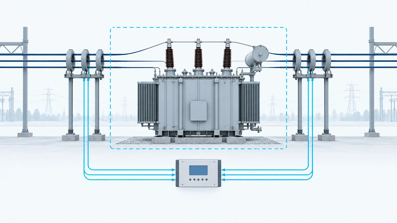
Correct transformer differential settings start by referring every winding current to a common relay base. Calculate winding full-load current, apply actual current-transformer (CT) ratios and relay connection factors, verify vector-group and zero-sequence compensation, then quantify normal mismatch from ratio steps, transformer taps, CT error and relay scaling. Only after that should you choose pickup, percentage restraint, high-set and inrush/overexcitation logic using the relay manual and project fault studies.
This is a study workflow, not a universal settings table. Actual values depend on transformer data, system grounding, CT performance, relay algorithm, fault levels, energization studies and the owner’s protection philosophy. Settings must be engineered, independently reviewed and commissioned by qualified personnel.
What the function must distinguish
Transformer differential protection compares currents entering and leaving a defined zone after compensating for the transformer’s ratio and phase shift. It should operate for internal faults while remaining secure for:
- normal load and permissible overload;
- external faults with CT saturation;
- transformer tap-changer range;
- magnetizing inrush;
- overexcitation;
- CT ratio error and unequal secondary burdens;
- vector-group phase displacement;
- zero-sequence current that does not transfer through the transformer in the same form;
- relay measurement and setting tolerances.
IEC 60255-187-1:2021 specifies functional and performance requirements for restrained and unrestrained differential protection of motors, generators and transformers. IEEE C37.91-2021 discusses practical application of power-transformer protection, including CT behavior during faults.
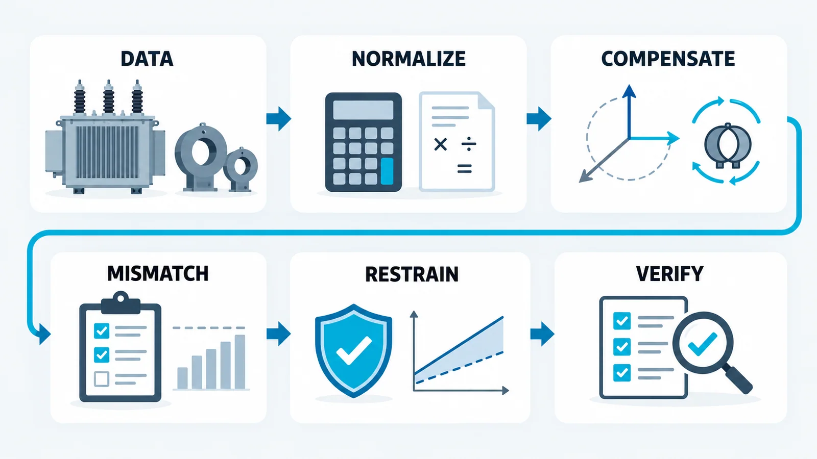
Step 1: define the protected zone and data set
Mark every CT and breaker that forms the differential zone on the one-line diagram. For each transformer winding collect:
- rated apparent power and cooling ratings;
- rated line-to-line voltage;
- vector group and phase sequence;
- grounded, impedance-grounded or ungrounded neutral arrangement;
- on-load/off-circuit tap range and step size;
- transformer impedance and available test data;
- CT ratio, class, polarity, location and secondary rating;
- CT lead resistance and connected burden;
- maximum load, external-fault and internal-fault currents;
- relay model, firmware, nominal current and compensation method;
- breaker status, trip matrix and lockout/reclose philosophy.
The IEC 60076 transformer specification guide explains why vector group, taps and impedance must be fixed in the equipment data before protection can be finalized.
Step 2: calculate winding rated currents
For a three-phase winding:
Iw = S / (√3 × VLL)
where:
- Iw is rated line current, A;
- S is three-phase apparent power, VA;
- VLL is rated line-to-line voltage, V.
Calculate every winding independently at the same MVA base. If multiple cooling ratings exist, state which rating defines the protection base and verify overload requirements separately.
Worked normalization example
Consider an illustrative 40 MVA, 115/13.8 kV, two-winding transformer. Ignore tertiary and tap effects temporarily.
High-voltage rated current:
IH = 40,000,000 / (√3 × 115,000) = 200.8 A
Low-voltage rated current:
IL = 40,000,000 / (√3 × 13,800) = 1,673.5 A
Assume CTs of 300/1 A on the high-voltage side and 2000/1 A on the low-voltage side. At transformer rated load, their raw secondary currents are:
IH,sec = 200.8 / 300 = 0.669 A
IL,sec = 1,673.5 / 2,000 = 0.837 A
Without relay scaling, the two inputs differ by about 20%. A numerical relay normally scales each input to a common internal base and compensates phase shift. The example demonstrates why matching CT nameplate ratios by intuition is insufficient; it does not prescribe a relay tap or pickup.
Step 3: apply relay-base scaling
For each winding, document a scaling factor that maps measured secondary current to a common per-unit value. A generic representation is:
Ipu,w = (Isec,w / Ibase,w) × Kconn,w × Kvector,w
where the connection and vector terms represent the relay’s actual implementation. Some relays ask for transformer and CT data and calculate compensation internally; others expose tap or matrix settings. Never duplicate compensation externally and internally.
At balanced rated load, the compensated positive-sequence currents should be equal in magnitude and opposed in the differential summation, subject to normal error.
Step 4: verify vector-group compensation
A delta-wye transformer introduces magnitude and angular relationships that the differential function must correct. Verify:
- transformer vector-group notation against measured/nameplate phase displacement;
- CT polarity and phase mapping;
- whether CTs are physically star/delta connected or all star-connected with numerical compensation;
- the relay’s phase-reference convention;
- compensation applied to each winding, including a tertiary;
- phase rotation and any nonstandard system connection.
Test with phasors, not only magnitudes. A wiring arrangement can show plausible current magnitudes while producing differential current because one phase or polarity is wrong.
Step 5: handle zero-sequence current explicitly
External ground faults can create zero-sequence current on a grounded-wye side that does not appear in the corresponding line currents on a delta side. Depending on the CT connection and relay algorithm, this component may need removal from the differential comparison.
Document:
- which windings can carry zero-sequence current;
- the transformer path for zero-sequence flux/current;
- whether the relay removes zero sequence numerically;
- whether physical delta-connected CTs already block it;
- how restricted earth-fault protection, if used, overlaps the zone.
Do not apply both physical and numerical compensation without verifying the relay design.
Step 6: build the steady-state mismatch budget
Estimate the maximum credible differential spill under load and through current. Keep deterministic and transient effects separate.
| Contributor | How to evaluate | Setting implication |
|---|---|---|
| CT ratio step | compare selected ratios with ideal ratios on common base | fixed mismatch at all loads |
| transformer tap range | calculate ratio deviation at extreme operating taps | operating mismatch varying with tap |
| CT ratio/phase error | use applicable CT accuracy data at burden/current | uncertainty in magnitude and angle |
| relay measurement tolerance | use relay technical manual | minimum margin above normal error |
| unequal lead/device burden | calculate and verify secondary burden | CT error and saturation risk |
| auxiliary CTs, if any | include ratio and phase errors | additional fixed/variable mismatch |
A simple percentage mismatch between two compensated magnitudes can be screened as:
m = |I1 − I2| / ((|I1| + |I2|)/2) × 100%
Use the relay’s own operate/restraint definitions for final settings. Different manufacturers calculate restraint current differently, so generic formulas cannot be copied into a settings file.
Step 7: model through-fault security and CT saturation
During an external fault, large equal primary currents should cancel. If one CT saturates more than the other, false differential current appears. Evaluate:
- maximum symmetrical and asymmetrical through-fault current;
- X/R ratio and remanence assumptions;
- CT class, ratio, excitation characteristics and secondary burden;
- fault duration and breaker failure scenarios;
- different CT designs/ratios across windings;
- relay saturation detection and restraint behavior.
IEEE C37.110-2023 covers CT characteristics, distortion/saturation causes and application to protective relaying. The correct response may involve CT selection, burden reduction or multi-slope restraint—not merely raising pickup.
Step 8: choose the characteristic from evidence
Transformer differential relays commonly provide some combination of:
- minimum differential pickup;
- one or more percentage-restraint slopes;
- restraint breakpoints;
- unrestrained/high-set differential element;
- inrush restraint or blocking;
- overexcitation restraint/blocking;
- waveform or CT-saturation logic.
The setting process should demonstrate:
- Sensitivity: the protected-zone fault study produces operating current above the characteristic for the minimum relevant internal fault.
- Load security: maximum load, tap and measurement error remain below pickup with margin.
- Through-fault security: external faults, including credible CT saturation, remain restrained.
- Transformer energization security: inrush cases are addressed using the relay’s supported logic and project energization evidence.
- Overexcitation security: expected V/Hz conditions do not cause undesired operation, without masking internal faults.
- High-set security: the unrestrained element is above credible external-fault spill and inrush while still useful for severe internal faults.
There is no universally correct pickup, slope or harmonic threshold. Use the relay manual, owner standard and study model for the installed system.
Step 9: document settings as a calculation chain
The settings report should allow another engineer to reproduce the result:
- one-line and zone boundary;
- transformer ratings, vector group, impedance and taps;
- CT ratios/classes/polarities and burden calculation;
- winding full-load currents;
- raw and compensated relay currents;
- vector and zero-sequence compensation choices;
- normal mismatch budget;
- minimum internal and maximum external fault cases;
- CT saturation study assumptions;
- pickup, slopes, breakpoints and high-set rationale;
- inrush/overexcitation logic and source evidence;
- trip matrix and interlocks;
- test plan and expected results;
- independent-review record.
Commissioning tests that close the loop
Before service, verify the complete protection chain:
- CT ratio, polarity, phase and secondary grounding;
- relay CT ratio and transformer data entries;
- steady load phasors and calculated differential/restraint quantities;
- vector compensation for each winding;
- zero-sequence response using approved secondary injection;
- characteristic points around pickup, slopes and breakpoints;
- inrush/overexcitation logic with relay-approved test methods;
- trip outputs, lockout and breaker paths;
- event records and alarms;
- setting-file/version control.
The current transformer installation and testing workflow covers safe CT secondary handling, burden, polarity and grounding. Secondary injection does not prove primary CT ratio/polarity or the entire trip chain by itself.
Stop conditions
Do not approve settings when any of the following remains unresolved:
- transformer vector group or tap range is provisional;
- CT ratio/class/burden data are missing;
- maximum external fault and minimum internal fault cases are unavailable;
- relay compensation convention is uncertain;
- zero-sequence treatment is not demonstrated;
- inrush/high-set security relies on a generic value;
- field phasors do not match the study;
- setting revisions are not controlled.