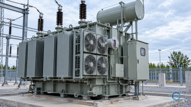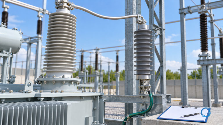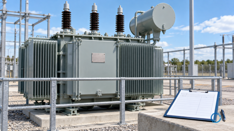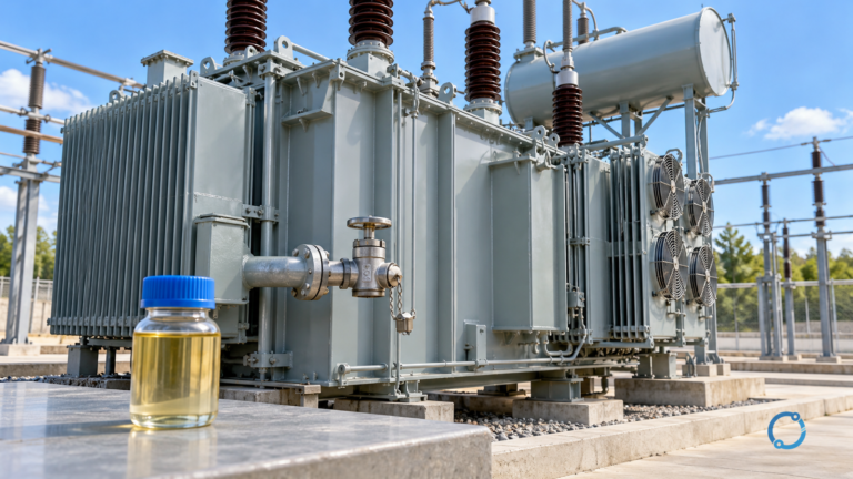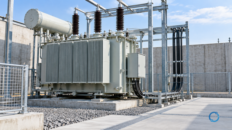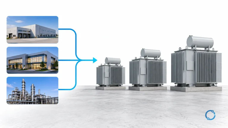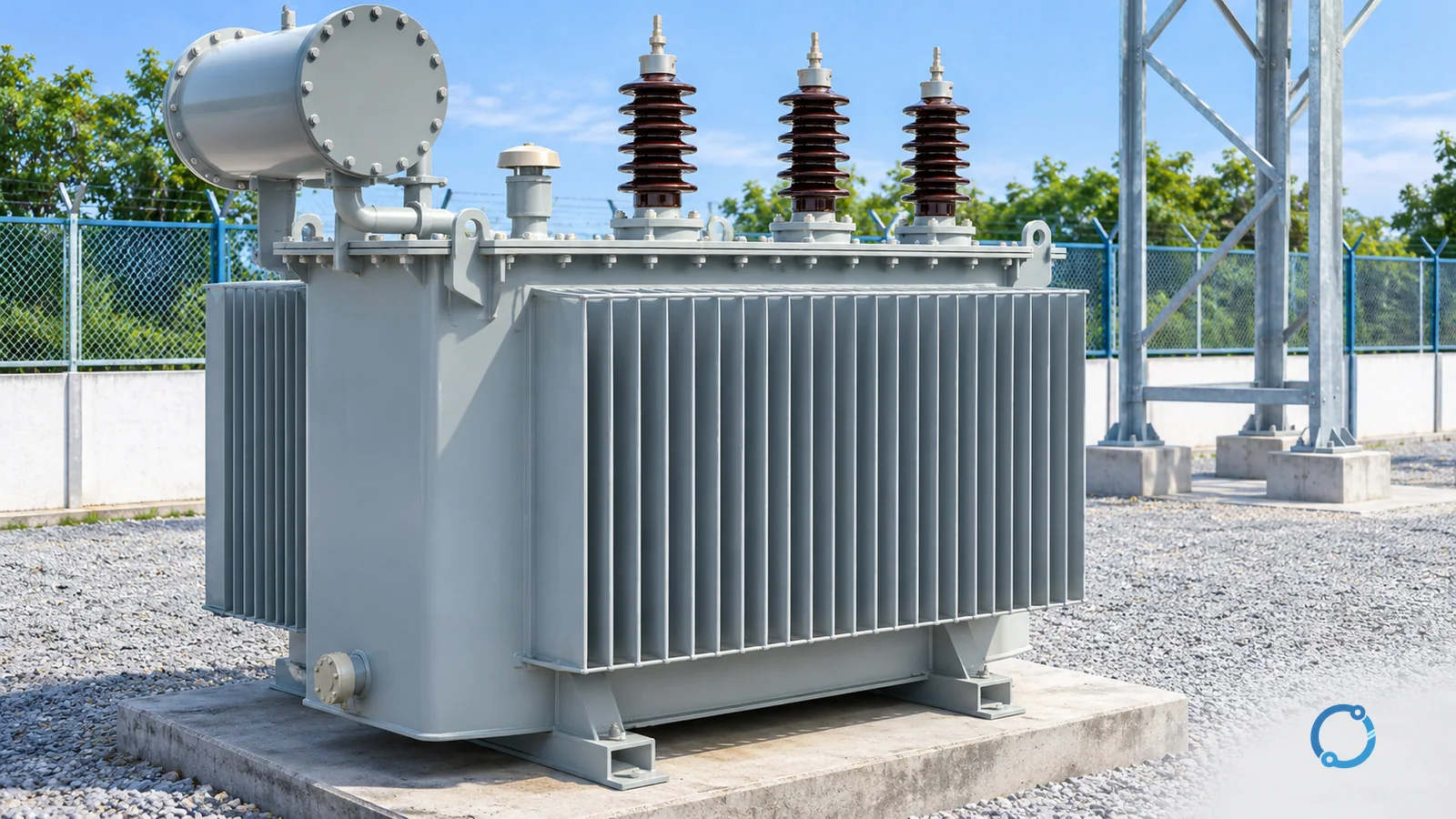
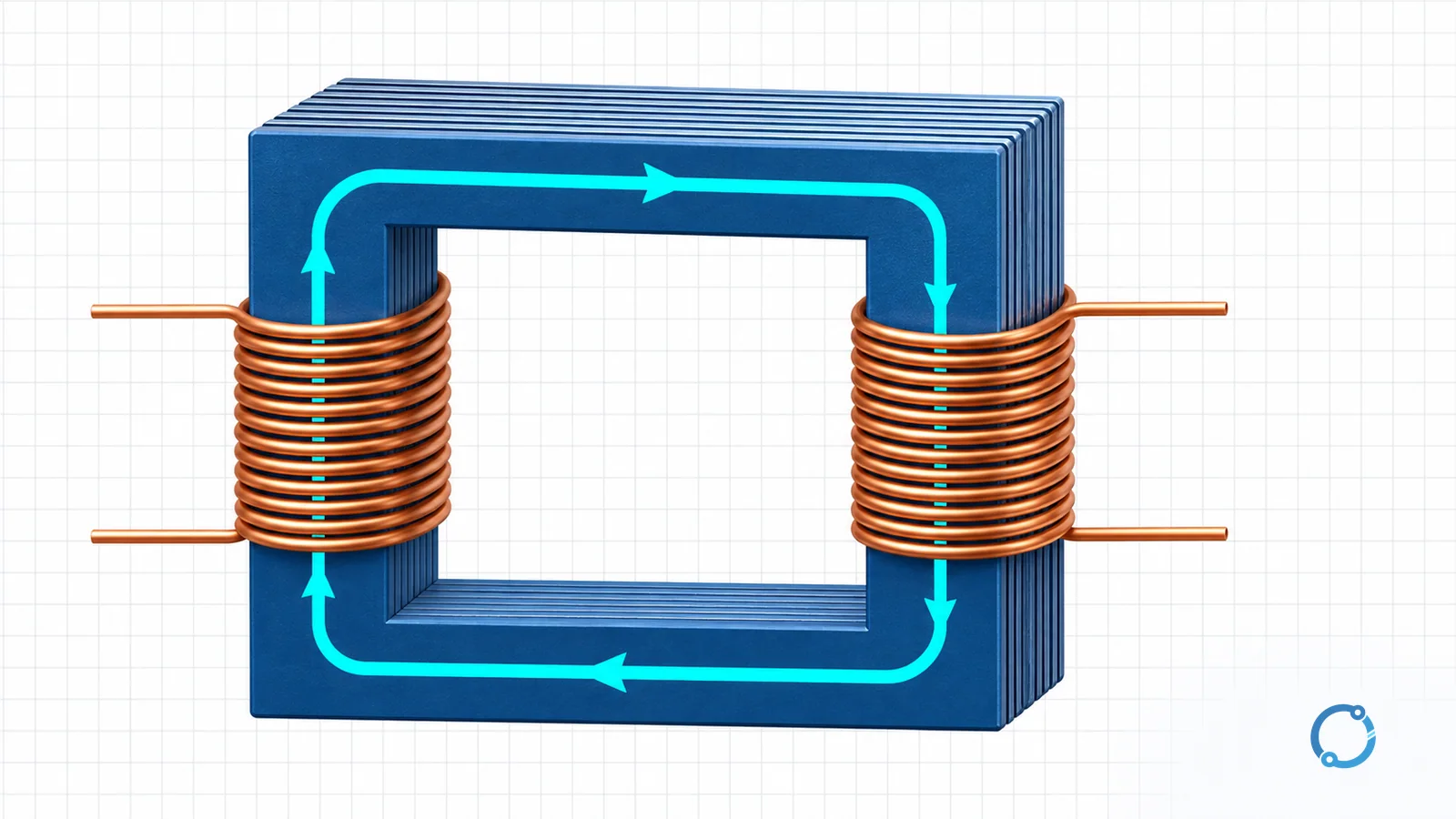
A transformer transfers electrical energy between two windings through a changing magnetic field. An alternating voltage applied to the primary winding produces an alternating current and a changing magnetic flux in the core. That changing flux links the secondary winding and induces a voltage there. The two windings are electrically separate in the usual two-winding transformer, but they are coupled through the shared magnetic path.
This is why a transformer can step voltage up or down without a continuous conductive connection between the windings. It is also why steady direct current does not provide continuous transformer action after the initial transient: once the current and flux stop changing, the induction mechanism that transfers energy to the secondary stops.
The U.S. Department of Energy transformer chapter describes the primary winding as the coil energized from an AC source and the secondary as the coil that delivers AC to the load. It also explains that the windings are linked by a varying magnetic flux.
Start with electromagnetic induction
Faraday’s law says that a changing magnetic flux through a coil induces an electromotive force (EMF). The induced voltage depends on the number of turns and the rate at which the flux changes. A stationary magnetic field alone does not produce a continuous induced voltage in a stationary winding; the field must change, or the coil and field must move relative to each other.
In a transformer, the primary current establishes flux in the magnetic core. Because the supply is alternating, the flux rises, falls, and reverses direction continuously. The same changing flux passes through the secondary winding, so the secondary sees an induced EMF even though it is not connected to the primary circuit.
The U.S. DOE electrical-science volume on magnetism introduces Faraday’s law and magnetic flux. The transformer chapter applies the same idea to two coupled windings.
What the core and windings do
The core
The core provides a low-reluctance path for magnetic flux. A higher-reluctance path would require more magnetizing current to establish the same flux and would allow more flux to leak outside the intended magnetic circuit. Transformer cores are commonly made from thin insulated steel laminations or other magnetic materials selected for the application. The insulation between laminations limits circulating eddy currents in the core.
The core does not create energy. It guides and concentrates the magnetic field that couples the windings. Real cores have losses, including hysteresis and eddy-current loss, so the transformer is not an ideal energy-transfer device.
The primary winding
The primary winding receives the source voltage. Its alternating current produces the changing magnetic flux. The winding has resistance, so some energy becomes heat, and the magnetic circuit requires a magnetizing current even when the secondary is open-circuited.
The secondary winding
The secondary winding is linked by the changing flux. An EMF is induced across it, and when a load is connected, current flows to the load. The secondary voltage depends on the primary voltage, the turns ratio, and the transformer’s real behavior under load.
The sinusoidal EMF equation
For a sinusoidal flux waveform, the RMS-induced EMF in a winding can be written as:
E = 4.44 x f x N x Phi_max
Where:
Eis the RMS induced EMF in volts;fis the frequency in hertz;Nis the number of turns in the winding;Phi_maxis the maximum magnetic flux in webers.
The 4.44 factor is approximately 2 pi / sqrt(2). It comes from differentiating a sinusoidal flux to obtain the induced EMF and then converting the sinusoidal result to an RMS value. The equation assumes a sinusoidal flux and a consistent set of units. A nonsinusoidal waveform, a distorted flux, or a different definition of the voltage requires a different analysis.
The equation shows why frequency matters. If the same winding is operated at a lower frequency while the flux is held constant, the induced EMF falls. In real transformer design, the relationship between voltage, frequency, and flux is one reason a transformer has a rated frequency and a rated voltage; those ratings cannot be treated as arbitrary operating points.
The turns ratio
For an ideal transformer with negligible losses and perfect coupling, the voltage ratio follows the turns ratio:
Vp / Vs = Np / Ns
Here, Vp and Vs are the primary and secondary voltages, and Np and Ns are the corresponding turn counts. The ratio is a model. A real transformer has winding resistance, leakage flux, magnetizing current, core loss, and temperature effects, so the measured secondary voltage changes with load and operating conditions.
The transformer kVA selection guide addresses a different question: how much apparent-power capacity the transformer needs for a load profile. The present article explains the mechanism, not the sizing decision.
Step-up example
Assume an ideal transformer has:
- primary voltage
Vp = 240 V; - primary turns
Np = 120; - secondary turns
Ns = 600.
Rearrange the turns-ratio relationship for the secondary voltage:
Vs = Vp x Ns / Np
Vs = 240 V x 600 / 120 = 1200 V
The secondary voltage is 1200 V in the ideal model. Because the secondary has more turns than the primary, this is a step-up transformer. The result is a voltage ratio, not a statement that the transformer can supply unlimited current or power.
Step-down example
Assume another ideal transformer has:
- primary voltage
Vp = 480 V; - primary turns
Np = 400; - secondary turns
Ns = 100.
Use the same relationship:
Vs = 480 V x 100 / 400 = 120 V
The secondary voltage is 120 V in the ideal model. The lower turns count makes this a step-down transformer. In a real unit, the output at load will differ because of impedance, losses, tap position, and supply conditions.
Why AC is required
A transformer needs a changing flux to induce a continuous secondary EMF. An AC source repeatedly reverses the primary current and therefore repeatedly changes the core flux. That changing flux is the coupling mechanism.
A steady DC source can produce a magnetic field when it is first connected, and the changing current during that transient can induce a temporary secondary voltage. Once the current reaches a steady value, the flux is no longer changing, so the continuous transformer action stops. A DC winding may also overheat if it is connected to a source that is not designed for that condition, because the winding’s resistance may be the only thing limiting current.
This does not mean a transformer can never be exposed to DC. It means the normal operating principle depends on alternating or otherwise changing flux. A DC component superimposed on an AC supply can shift the operating point and is a separate design and protection concern.
Ideal model versus real transformer
The turns-ratio equations are a useful first model, but a real transformer includes:
- copper loss in the primary and secondary windings;
- core loss from hysteresis and eddy currents;
- leakage flux that links one winding more strongly than the other;
- magnetizing current needed to establish the core flux;
- winding resistance and impedance;
- temperature rise, cooling, and insulation limits;
- harmonic and transient behavior;
- tap positions and winding connections that change the voltage relationship.
Those effects do not invalidate the mechanism. They explain why the nameplate ratio is not the same as a measured secondary voltage at every load. The guide to how electricity is generated shows where transformers sit between generation and the distribution system; the transformer rating-basis article explains why apparent-power rating is not the same as a simple voltage ratio.
For three-phase work, the winding connection and line-versus-phase relationship matter. The delta transformer calculation guide and wye transformer calculation guide cover those separate calculation tasks.
A quick check for transformer calculations
- Identify which winding is primary and which is secondary for the stated operating direction.
- Use a consistent voltage basis: RMS or peak, line or phase, as appropriate.
- Count the turns for the same winding definition.
- Apply the ideal ratio only as a first check.
- Compare the result with the transformer’s actual rating, connection, tap, and load data.
- Do not infer insulation adequacy, short-circuit strength, or protection settings from the turns ratio alone.
FAQ
How does a transformer transfer energy without a wire connection?
The primary winding creates a changing magnetic flux in the core. The flux links the secondary winding and induces an EMF there. Energy is transferred through the magnetic field, not by a continuous conductor between the two windings.
What is the transformer EMF equation?
For sinusoidal operation, E = 4.44 x f x N x Phi_max, where E is RMS volts, f is hertz, N is turns, and Phi_max is maximum flux in webers. The factor depends on the waveform.
What is the turns ratio?
For an ideal transformer, Vp / Vs = Np / Ns. More secondary turns than primary turns gives a step-up voltage ratio; fewer secondary turns gives a step-down ratio.
Why does a transformer need AC?
AC continuously changes the magnetic flux, which induces a continuous secondary EMF. Steady DC produces no sustained changing flux after the initial transient, so it does not provide normal transformer action.
Is the turns-ratio result the exact secondary voltage?
No. It is an ideal first estimate. Winding resistance, leakage, core loss, load current, temperature, taps, and supply conditions can change the measured voltage.