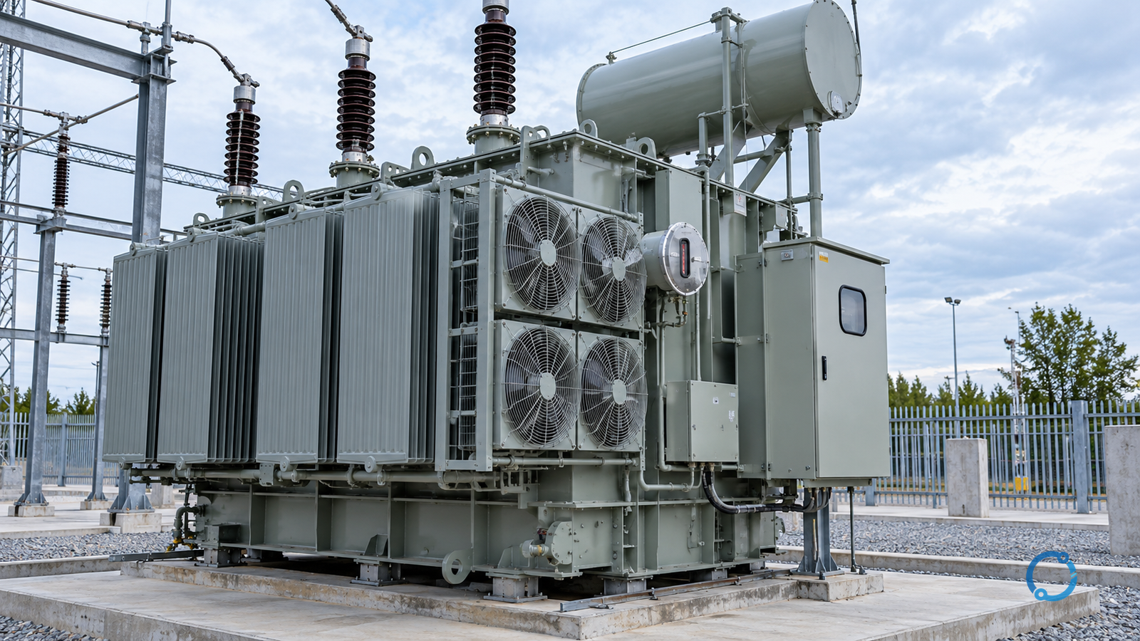
A transformer nameplate gives a compact summary of a conditional rating. It does not say that any combination of current, ambient temperature, cooling state and tap position is acceptable merely because the apparent power remains below the number printed on the tank.
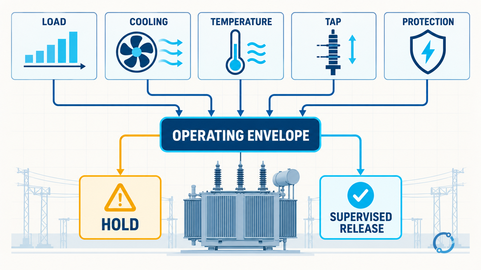
Loading decisions become difficult because several limits move at once:
- higher current increases conductor and winding loss;
- ambient temperature changes the rate at which heat leaves the equipment;
- a stopped fan or pump changes cooling from an assisted class to a different thermal state;
- tap position changes the voltage ratio and the current needed for the same power transfer;
- top-oil temperature responds more slowly than winding temperature;
- protection settings may have been calculated for a different tap or source impedance;
- insulation ageing depends on temperature and time, not on a single alarm threshold.
IEC 60076-1 defines the general requirements and rating framework for power transformers. IEC 60076-2 addresses temperature rise for liquid-immersed transformers, while IEC 60076-7 provides loading guidance. Together they tell an engineer to evaluate the transformer as a thermal system. They do not justify copying a generic overload percentage into a site procedure.
The useful question is not “What is the transformer overload limit?” It is:
For this transformer, load profile, ambient condition, cooling state and tap position, which limits are being approached, what evidence supports the assumed cooling, and how will the condition be supervised and released?
The rating is a set of simultaneous conditions
The apparent-power rating can be expressed as:
\begin{equation}
S = \sqrt{3} \times V \times I
\end{equation}
for a balanced three-phase system, with voltage and current stated on the same basis. The equation is simple. The conditions surrounding (V), (I) and (S) are not.
At a fixed apparent power, raising or lowering the secondary no-load voltage with a tap changer changes the current that the connected load draws if the load behaves like an impedance. It also changes the current needed to deliver the same real or apparent power. A tap position that improves voltage may therefore worsen current, thermal margin or protection coordination.
Nameplate kVA, voltage ratio, frequency, cooling class, temperature rise, winding connection, impedance and tap range belong to one rating map. Treating each as an independent field is a common source of error.
Separate the five operating layers
A defensible assessment records five layers.
1. Load
Record apparent power, active power, reactive power, voltage, current, power factor and duration. Distinguish steady-state demand from a starting, welding, furnace, motor or cyclic load. A transformer can tolerate a high short-time load differently from a sustained load at the same peak.
Load logging should capture the full interval, including morning/evening peaks, duty cycles and any event that changed cooling or topology. A single spot reading is only one point on the thermal curve.
2. Heat removal
Record the design cooling method, current operating state and the actual environment. For liquid-immersed equipment, natural oil circulation and forced cooling may correspond to different nameplate ratings or different permissible loading assumptions. For dry-type transformers, enclosure, room ventilation, altitude and dust have related but distinct effects.
Check the physical assumptions:
- fan and pump availability;
- radiator or cooling coil cleanliness;
- room or enclosure air path;
- recirculation of hot air;
- sun and radiant heat;
- ambient temperature and its daily pattern;
- water temperature and flow for water-cooled equipment;
- nearby heat sources or obstructions.
A cooling command that has been issued does not prove that cooling is available. Command status, operating feedback, temperature response and inspection evidence are separate signals.
3. Temperature
Oil temperature, winding temperature and hot-spot temperature answer different questions. IEC 60076-2 distinguishes rated temperature-rise conditions, but a measured top-oil temperature does not prove the winding hot spot is acceptable. The transformer’s loading guide uses a thermal model with preload, load loss, oil time constant and winding regulation.
IEC 60076-7 is useful because it treats loading as a time-dependent thermal process. A step increase in load produces a gradual oil response and a faster winding response. A temporary overload may be limited by winding hot-spot temperature even while the oil gauge still looks comfortable.
Record:
- sensor type, location and calibration status;
- top-oil and bottom-oil temperatures where provided;
- simulated or directly measured winding temperature;
- ambient temperature;
- pre-load and load history;
- fan/pump state;
- alarms, trips and response time;
- steady-state versus transient behaviour.
Do not compare readings from differently located or compensated sensors as if they were interchangeable.
4. Tap position
A tap changer changes the effective turns ratio. On a no-load tap changer, the transformer must be isolated and verified before changing position. An on-load tap changer requires its own operational, maintenance and protection controls; it is not a free adjustment used to chase a fluctuating load.
Record the tap number and the corresponding voltage and current table. Confirm:
- the tap position against the physical indicator;
- the control and indication circuit where present;
- the permitted load at that tap;
- the effect on secondary voltage;
- the effect on protective-relay reach and current settings;
- the effect on parallel-transformer circulating current;
- the effect on downstream motor starting and cable voltage drop.
Parallel transformers require particular care. A tap mismatch can create a circulating current before useful load is supplied. Equal nameplate voltage ratios are not enough if tap definitions, impedance, phase displacement or control are mismatched.
5. Protection and operating policy
The protection scheme is part of the operating limit because it defines how an abnormal thermal or electrical state is detected. Check winding and oil temperature trips, pressure devices, differential protection, overcurrent, earth fault and gas monitoring only to the extent supported by the equipment design and site instructions.
An operating decision should identify:
- who authorises temporary loading;
- how long the condition may last;
- which temperature or current alarm defines escalation;
- whether cooling redundancy is available;
- whether the tap change needs a protection study update;
- what evidence ends the event;
- how the event is recorded.
Without these rules, a short-term exception becomes an undocumented new normal.
Why a kVA-only check is incomplete
Suppose a 1,000 kVA transformer is operating at 960 kVA, which appears to be only 96% of nominal rating. That observation alone does not establish margin.
The same 960 kVA can be less demanding or more demanding depending on:
- whether the declared ambient condition matches the actual room;
- whether all cooling equipment is available;
- whether the tap position changes current;
- whether the load is steady, cyclic or starting;
- whether the transformer is already warm from a preceding event;
- whether the current is balanced across phases;
- whether harmonics add winding and stray losses;
- whether the winding hot spot is rising after the kVA reading;
- whether protection settings are correct for the current tap.
A transformer at 96% of apparent-power rating with failed cooling and a rising winding temperature may be closer to a stop condition than an identical transformer at 100% with all cooling available and stable temperatures.
Worked boundary example
Consider a transformer with only these project-recorded facts:
- rated apparent power: (S_r);
- rated voltage pair at tap A: (V_{1A}) and (V_{2A});
- measured balanced load at tap A: (I_A);
- measured load at a proposed tap B: (I_B);
- actual ambient is above the rating assumption;
- one cooling stage is unavailable;
- the winding-temperature model results are not yet validated.
At tap A, the measured apparent power is:
\begin{equation}
S_A = \sqrt{3} \times V_{2A} \times I_A
\end{equation}
At tap B, use the measured secondary voltage and current, not the nameplate no-load voltage:
\begin{equation}
S_B = \sqrt{3} \times V_{2B} \times I_B
\end{equation}
Suppose the calculations show (S_B < S_r). That proves only that the apparent-power number is below nominal. It does not clear the condition. Before authorising tap B with reduced cooling and high ambient, obtain:
- the manufacturer’s or loading-guide thermal case for that cooling state;
- the actual pre-load and expected duration;
- the winding and oil temperature trajectory;
- the protection setting review for tap B;
- the parallel-operation check, if another transformer is connected;
- the operating authority and a defined recovery point.
If any item is missing, the correct decision is a controlled hold or a lower load, not a rounded statement that 96% is “close enough.”
Cooling class is not a permanent guarantee
The letters or digits in a cooling designation describe how the oil and external medium circulate. They do not guarantee that every fan, pump, valve or control is operating now.
At a minimum, confirm the relationship between:
- cooling equipment state;
- nameplate rating at that state;
- actual ambient;
- control mode;
- alarm response;
- loss of auxiliary power;
- maintenance test result.
A temperature rise measured with forced cooling is not transferable to a condition in which that cooling is unavailable. Likewise, cleaning a blocked radiator can restore a foundation assumption rather than “increase the rating” as an informal field claim.
Tap positions and load current
Tap selection is often treated as a voltage problem separate from loading. It is not.
For a balanced load, the current relationship is approximately inverse with voltage for constant apparent power:
\begin{equation}
\frac{I_B}{I_A} \approx \frac{V_A}{V_B}
\end{equation}
This is an approximation, not a method for setting taps. Real loads may draw nearly constant current, nearly constant impedance, or a mixture. Motors, rectifiers, capacitor banks and transformers respond differently as voltage changes.
Use the actual load model and verify the transformer’s permitted tap rating. A nominal winding may have a reduced current rating at an extreme tap because leakage flux, winding gradients or cooling conditions change.
Also check the protection study. A tap change can alter the voltage seen by relays, the current at the protected terminals and the reach of distance elements. A tap position that is electrically convenient for the load may be outside the approved protection envelope.
How to assess a short-term overload
Use a repeatable sequence:
Gate 1: define the event
Record the present load, predicted step, duration, expected cycle and reason the transformer must carry it. A transformer model is not a substitute for the operating plan.
Gate 2: verify the physical condition
Confirm cooling availability, oil level, leaks, blocked airflow, abnormal noise, visible overheating and the latest condition-monitoring evidence. Do not rely on an earlier “normal” inspection if the present cooling state has changed.
Gate 3: reconstruct the pre-load
A hot transformer starts an event from a different thermal state. Record the load and temperature history for the preceding hours where practical. A short-term limit cannot be estimated from the peak alone.
Gate 4: run the thermal case
Use the manufacturer’s loading guide, an approved model or a conservative project method. Record the ambient, cooling situation, initial temperature and time step. State whether the result is based on measured winding temperature, simulated hot spot or top oil approximation.
Gate 5: check the electrical system
Verify voltage limits, current, tap effects, neutral current, harmonic distortion, parallel transformers, tap-changer duty, cable loading, breaker protection and downstream voltage. A thermally acceptable transformer can still create an unacceptable system voltage.
Gate 6: define supervision
Set the measurement interval and the escalation triggers. Make someone responsible for stopping the event if a temperature, current or gas condition changes. Do not rely on “we will watch it” without a named observer and a defined action.
Gate 7: restore and investigate
After the event, return cooling and tap control to the approved state, verify protection and alarms, record maximum temperatures and check for oil or gas changes. If the event revealed a failed cooling stage or abnormal temperature, initiate maintenance and root-cause checks.
Temperature records that actually support a decision
A screenshot of a single gauge is not a thermal record. A useful record includes:
| Time | Load | Ambient | Oil temperature | Winding indication or model | Cooling state | Tap | Event note |
|---|---|---|---|---|---|---|---|
| Start | Measured | Measured | Measured | Basis stated | Verified | Verified | Cause of change |
| Peak | Measured | Measured | Measured | Basis stated | Verified | Verified | Alarm or action |
| Recovery | Measured | Measured | Measured | Basis stated | Verified | Verified | End condition |
The record must state whether values were measured, simulated or inferred. Mixing a simulated winding temperature with a measured oil value and presenting both as direct measurements undermines the decision.
Faults that resemble loading problems
The transformer may be hot or overloaded because something else is wrong. Do not treat every high temperature as a legitimate load event.
Possible contributors include:
- blocked cooling ducts or radiator fins;
- fan or pump failure;
- control set-point error;
- unbalanced or circulating current;
- harmonic loss;
- failed tap or connection;
- restricted enclosure ventilation;
- high ambient from an adjacent heat source;
- winding fault or deteriorated insulation;
- instrumentation offset;
- repeated motor starting or cyclic duty.
Dissolved-gas analysis, insulation resistance, winding resistance or other diagnostic tests should follow their own evidence rules. A load calculation cannot close a suspected internal fault.
A practical operating-envelope procedure
For each transformer asset, maintain a one-page operating envelope containing:
- identity, rating and tap table;
- cooling configurations and the corresponding evidence;
- ambient and installation basis;
- temperature measurement and modelling method;
- normal, warning and emergency supervision limits;
- protection and alarm settings;
- permissible tap positions and control ownership;
- parallel-operation rules;
- short-term loading authorisation path;
- recording and close-out requirements.
The envelope should be based on the actual installation, not copied between transformer sizes. A family look-up can help orient the investigation, but it cannot replace the product data and the project’s thermal basis.
How to review a proposed overload
A strong review note can be short:
The proposed load is within the calculated short-term case at the recorded ambient and cooling state for the stated duration. Winding hot-spot and top-oil assumptions are documented. Tap position and protection have been checked. Cooling failure is monitored, and the operating team will reduce load if the agreed trigger is reached.
If the note instead says:
The transformer is 10% below rating, so the overload is acceptable.
the evidence is insufficient. The second statement does not identify heating, cooling, duration, ambient, tap or protection.
Dry-type transformers need an equivalent, not copied, assessment
The same principle applies to dry-type transformers, but the evidence changes. Winding temperature sensors, enclosure airflow, room ventilation, altitude, dust and adjacent heat sources may matter more directly than oil temperature and oil circulation. A section that is physically clean can still have a recirculating hot-air path or a cooling assumption that no longer matches the installation.
Do not take a liquid-immersed loading curve and apply it to a dry-type unit. Use the dry-type product data, insulation class, temperature-rise basis, enclosure instructions and approved engineering method. Record whether measured temperatures come from embedded winding detectors, simulated values, thermal imaging or room sensors. These sources answer different questions.
When an enclosure is modified, filters are blocked or an adjacent heat source is introduced, review the thermal case as an engineering change. The transformer’s nameplate has not changed, but the heat-removal assumptions may have.
Final rule
Transformer loading is a state-dependent decision. The safe sequence is to establish the asset identity, verify the actual cooling and ambient conditions, reconstruct the load and thermal history, review the tap and protection basis, run the appropriate thermal case, supervise the event and close it with records.
The nameplate is the starting point, not the answer. For related context, read transformer kVA rating basis, transformer kVA selection and load duty, IEC 60076 transformer specification, transformer impedance for short-circuit calculations and transformer DGA results explained.