
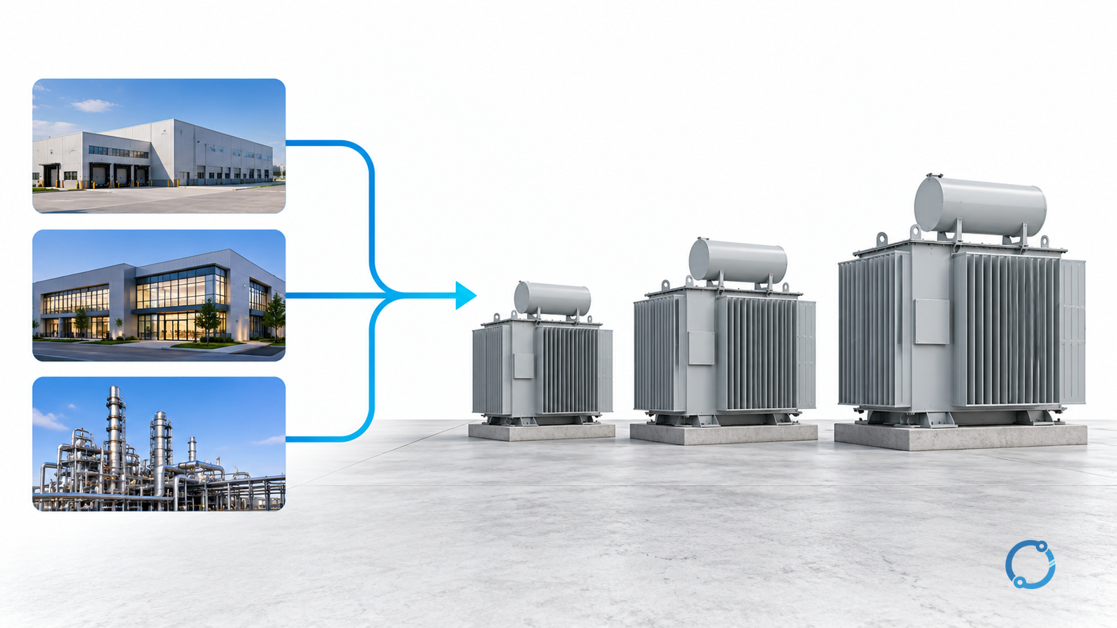
To size a transformer, start with a documented load profile in kVA, then compare candidate ratings against the thermal, voltage, harmonic, motor-starting, fault and environmental conditions that the transformer will actually see. A peak kW reading multiplied by an arbitrary percentage is not a sizing study.
This workflow covers a new or replacement two-winding industrial distribution transformer. It produces a shortlist and a verification record, not a final purchase decision. The transformer must still be specified to the applicable product standard and checked with the surrounding switchgear, protection and installation requirements.
Step 1: Fix the system boundary
Write down the source voltage, transformer winding voltages, frequency, phase arrangement, grounding method and the downstream system. Identify which loads are inside the transformer boundary and which are supplied elsewhere.
Then record the operating states that must work:
- normal production;
- maximum credible demand;
- night or low-load operation;
- standby generator or alternate supply;
- one transformer out of service;
- planned growth;
- motor starting or process restart;
- harmonic-rich loads and other nonlinear equipment.
The distribution substation basics guide places these inputs in the larger power system. Do not size a transformer in isolation from the switchgear, cables and protection that will carry the same load.
Step 2: Build an apparent-power load schedule
For each load or group, record real power, displacement power factor, duty cycle and any harmonic content. For sinusoidal groups:
S = P / PF
Do not add equipment kW and call it transformer kVA. Add the real and reactive components separately when the data permit, then combine them vectorially:
S = sqrt(P_total squared + Q_total squared)
or use the actual interval kVA from metering. Harmonic distortion can make apparent power and current higher than a simple fundamental-frequency calculation suggests; include measured data or a study when nonlinear loads are material.
Illustrative load-profile comparison
The following values are invented to demonstrate arithmetic:
| State | Real power | Displacement PF | Apparent power |
|---|---|---|---|
| Normal | 560 kW | 0.88 | 636.36 kVA |
| Peak | 720 kW | 0.92 | 782.61 kVA |
| Night | 180 kW | 0.95 | 189.47 kVA |
At 400 V, the 782.61 kVA peak corresponds to approximately 1,129.60 A line current:
782,610 / (sqrt(3) x 400) = 1,129.60 A
A 1,000 kVA candidate would be at about 78.3% of its apparent-power rating during that peak state, before any extra allowance:
782.61 / 1,000 = 0.783
That percentage is descriptive, not permission to load the transformer to 100% indefinitely. Ambient, cooling, starting temperature, load duration, harmonics, voltage limits and contingency requirements still need to be checked.
Step 3: Set the planning allowance with reasons
Add a future-load or contingency allowance only when a planning basis supports it. Label the basis:
- known committed load;
- measured historical peak;
- documented future expansion;
- redundant-supply requirement;
- short-duration process growth;
- voltage-regulation or starting reserve.
Do not hide several different allowances inside a single “20% safety factor.” A 20% allowance for future growth is not the same as an emergency overload rating, an ambient derating allowance or a motor-starting voltage-drop allowance.
Each candidate should show:
Required planning kVA = measured or calculated demand + justified planning additions
Then compare that quantity with the actual rating basis of each transformer. The transformer rating basis guide explains why the plate value must stay attached to its cooling, voltage and temperature conditions.
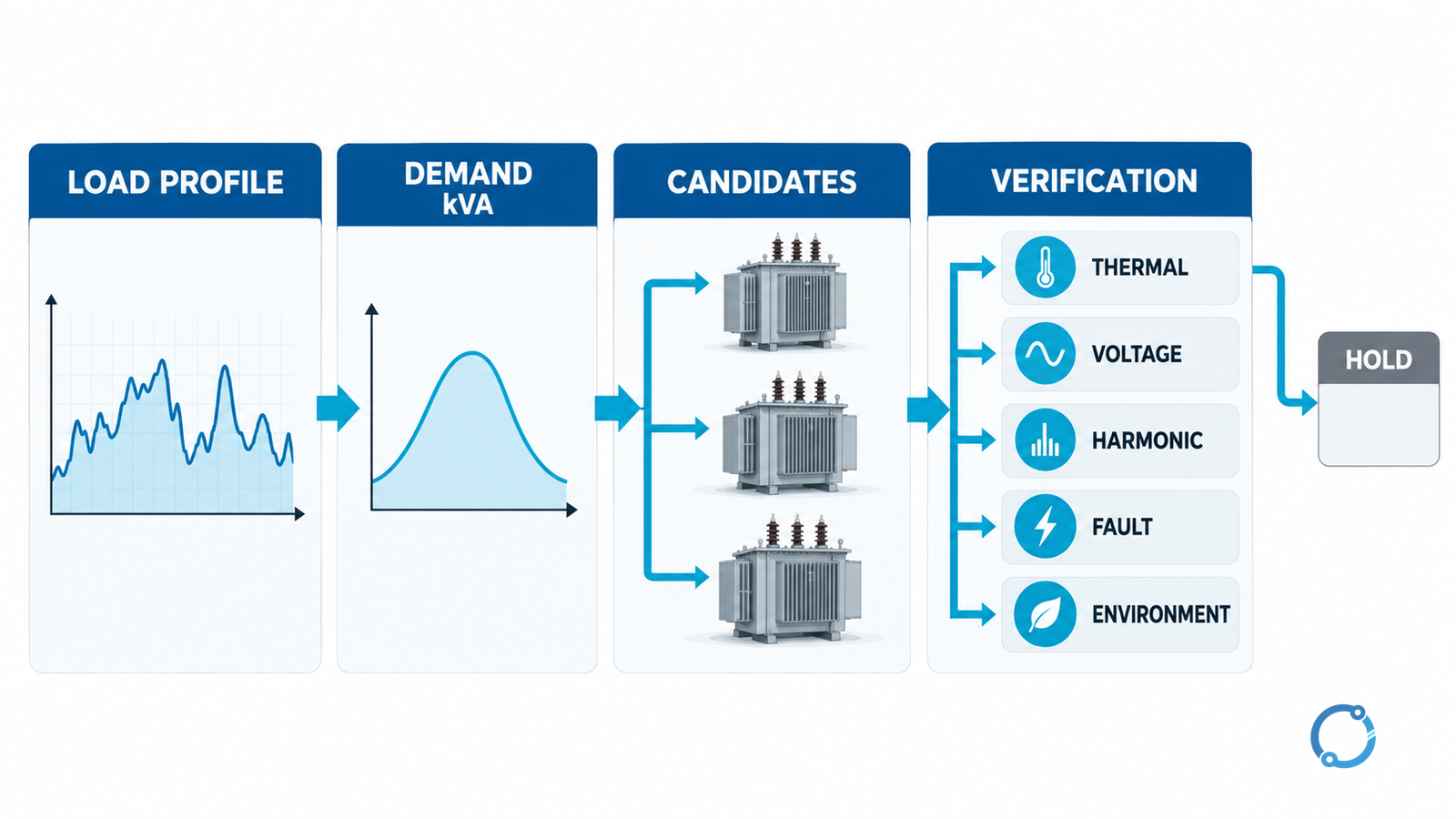
Step 4: Apply thermal and environmental gates
For every candidate, obtain the rating in the proposed cooling state and the ambient assumptions for the actual site. Ask what happens when fans or pumps are unavailable and how long the design permits a transition.
Check:
- normal and peak load duration;
- initial winding and liquid temperatures;
- site maximum and minimum ambient temperature;
- enclosure, room or outdoor placement;
- solar exposure and restricted airflow;
- altitude and other environmental conditions;
- the permitted temperature basis for the transformer family.
The IEC 60076-1 catalog identifies general service conditions and ratings. The IEC 60076-7 catalog addresses loading and thermal ageing for mineral-oil-immersed transformers; dry-type units require the applicable dry-type references and design data. Do not apply one family’s overload table to the other.
If the load exceeds the continuous rating, a short emergency state may still be possible, but the claim needs actual thermal evidence, duration, cooling state and consequences. This article does not supply a universal emergency percentage.
Step 5: Check voltage, harmonics and motor starting
Transformer impedance creates voltage drop as load current flows. Motor starting creates a transient current and voltage dip that may be outside a normal running-load calculation. Short-circuit impedance and source strength also determine how much starting voltage the motor receives.
Treat motor starting as a separate transient task: record the motor and starter data, source impedance, voltage-dip limit and acceleration requirement, then verify the candidate instead of applying one universal size ratio. For harmonic-rich loads, obtain measured spectra or a study that represents the actual current waveform. A transformer can be thermally stressed by harmonic loss and can be affected by neutral and zero-sequence currents. Do not choose a larger unit solely because a design has more kVA; the connection, harmonic mitigation and protection architecture matter.
Step 6: Verify fault duty and protection
A transformer’s impedance limits fault current, but the available fault level on the secondary still depends on the source, transformer, cable, parallel paths and operating modes. Check the interrupting, making and short-time withstand duty of the proposed switchgear and the coordination of the protective devices.
The IEC 61439-1:2020 catalog provides the low-voltage assembly general framework used with the relevant product part. A transformer with a suitable kVA rating does not prove that the downstream assembly can withstand the prospective fault. The overcurrent relay coordination worked example demonstrates why both minimum and maximum fault cases need checking.
Step 7: Compare standard candidates, not catalog slogans
Once the required planning kVA is known, compare a small number of candidates on a common basis:
| Decision gate | Evidence to record | Hold or reject trigger |
|---|---|---|
| Continuous thermal duty | Rating at the actual ambient and cooling state; load profile | Missing thermal basis or expected continuous overload |
| Emergency or contingency duty | Duration, starting temperature, accepted loading evidence | Unsupported emergency duration or cooling dependency |
| Voltage regulation | Impedance, tap range, operating voltages, starting study | Voltage limits cannot be met |
| Harmonics and neutral duty | Load spectrum, winding and neutral arrangement, study | Undefined distortion or fault path |
| Fault duty | Prospective current, assembly withstand, protective coordination | Equipment or coordination evidence missing |
| Physical installation | Ambient, enclosure, ventilation, access, sound and fire requirements | Site cannot accommodate the design |
| Losses and operating cost | No-load, load-loss and auxiliary data on a common basis | Incomparable loss basis |
This table is a selection framework, not a ranking of brands. A candidate that passes the continuous thermal row can still be excluded by fault duty, voltage regulation or physical constraints.
Step 8: Issue a traceable selection record
The final record should identify:
- the load schedule and metering period;
- every load-state assumption and harmonic input;
- the candidate ratings and their cooling/ambient basis;
- continuous and contingency results;
- voltage, starting and protection studies;
- fault duty and assembly evidence;
- physical and environmental acceptance;
- unresolved holds, their owners and the decision date.
“The load is under the transformer rating” is not a complete conclusion. It is one gate. The engineering release is the point where every gate has an accepted result and the remaining assumptions are visible.
Before purchase, turn the selected candidate into a proper equipment schedule with the IEC 60076 transformer specification checklist. Before energization, verify the actual installation and protective settings through the responsible commissioning process.