
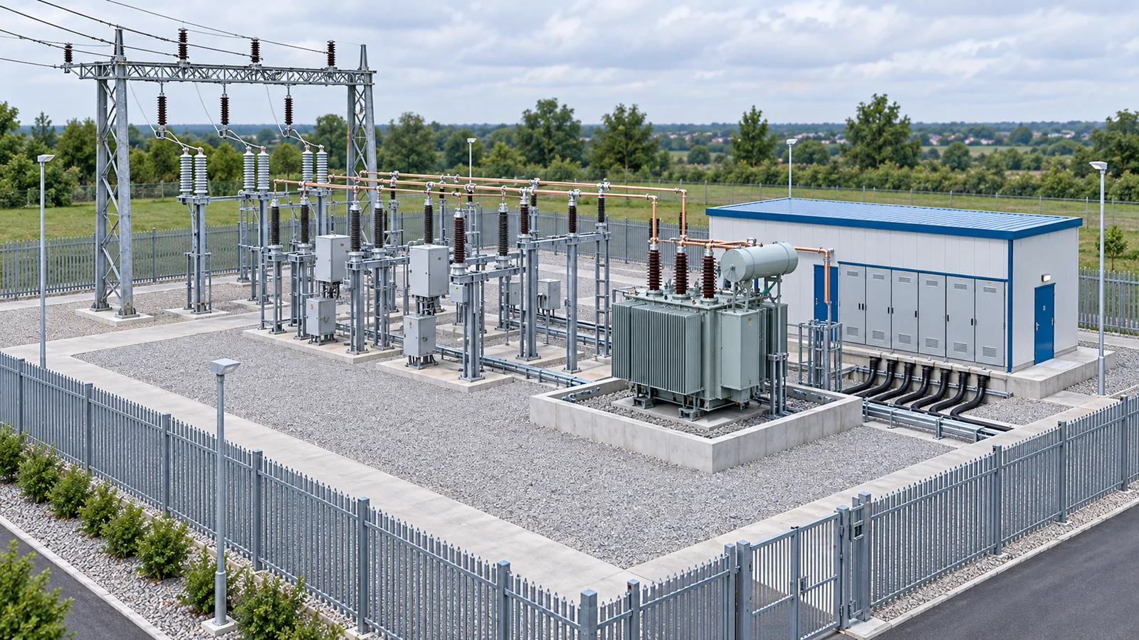
A distribution substation receives electrical power at one voltage, switches and protects it, usually transforms it to a lower distribution voltage, and sends it through multiple outgoing feeders. The transformer is central, but a working substation is a coordinated system of busbars, breakers, instrument transformers, surge protection, relays, control power, communications, grounding, civil works, and operating procedures.
This article explains that system boundary. It is not a construction specification or authorization to enter, operate, or maintain a substation.
Where a distribution substation sits in the grid
The common power path is:
incoming subtransmission or primary line → switching and protection → power transformer → distribution bus → feeder breakers → distribution circuits
Some substations have two or more transformers, multiple buses, bus ties, voltage regulators, capacitor banks, reactors, or distributed-energy connections. Industrial substations may feed plant switchgear rather than public distribution circuits. A compact unit substation may combine functions that an outdoor utility station separates physically.
The U.S. Department of Energy’s electricity-industry primer describes transformers as the means of converting voltage levels for efficient delivery. OSHA’s substation overview adds an operational perspective: substations can be indoor or outdoor, metal-clad or open-bus, and can serve as switching points, voltage-transformation points, and sources of distribution circuits.
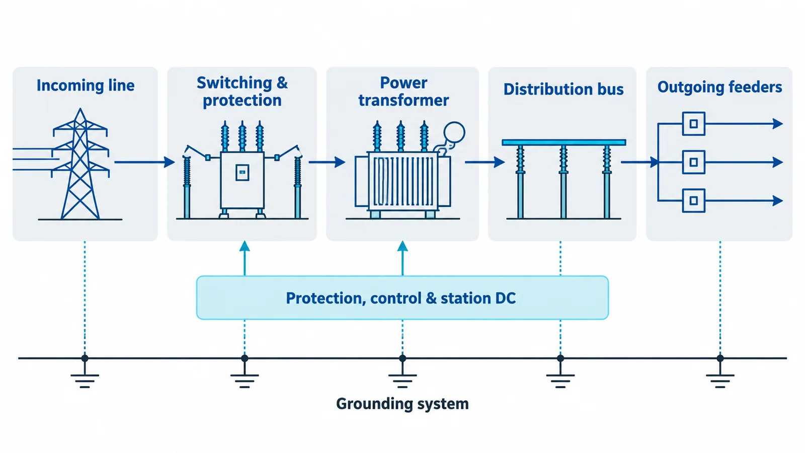
The main equipment and what it does
| Function | Typical equipment | Design question |
|---|---|---|
| Receive and isolate supply | Line entrance, disconnectors, switches, circuit breakers | What sources and backfeeds can energize the station? |
| Limit overvoltage | Surge arresters, shielding, insulation coordination | What lightning and switching stresses must be managed? |
| Measure system quantities | Current transformers, voltage transformers or sensors, meters | What accuracy, insulation, burden, and protection performance are required? |
| Interrupt faults and load | Circuit breakers, load switches, fuses | What normal current, fault current, switching duty, and transient recovery voltage apply? |
| Transform voltage | Power transformer, tap changer, cooling system | What MVA, ratio, impedance, vector group, duty, losses, and overload profile apply? |
| Collect and divide circuits | Busbars, bus couplers, bus sectionalizers | What current, short-time withstand, reliability, and maintenance strategy are required? |
| Protect and automate | Relays, trip circuits, interlocks, automation controller | Which faults must be detected, and what equipment must trip? |
| Supply control systems | Station battery, charger, AC auxiliary board, DC board | Will tripping, protection, communication, and emergency systems operate after loss of AC supply? |
| Control voltage and reactive power | Regulators, on-load tap changer controls, capacitor banks, reactors | How will voltage and reactive demand change with load and network configuration? |
| Keep people and equipment at a controlled potential | Ground grid, bonds, fences, crushed rock or other surface layer | Are touch and step voltages controlled for credible faults? |
The incoming side
The incoming line may be overhead, underground, or connected through gas-insulated or air-insulated equipment. The entrance arrangement establishes a controlled transition from the network to the station. Its design considers system voltage, basic insulation level, clearances, lightning exposure, fault level, conductor mechanical loads, pollution, altitude, and maintainability.
Disconnectors provide an isolating function under the conditions for which they are rated; they are not automatically equivalent to circuit breakers. A switching device may be able to make or break load current, fault current, charging current, or only specified limited currents. Device duty must be verified from the applicable product standard and system study.
The power transformer
The transformer changes voltage and contributes impedance that limits fault current. Its important system interfaces include:
- rated power and cooling stage;
- high- and low-voltage ratios and tap range;
- vector group and neutral arrangement;
- percentage impedance and zero-sequence behavior;
- insulation level and surge-protection coordination;
- loss evaluation, temperature rise, ambient conditions, and expected loading;
- protection such as differential, overcurrent, earth-fault, temperature, pressure, and gas-based functions where applicable;
- fire containment, oil management, separation, and access where a liquid-filled unit is used.
A transformer rating cannot be selected from peak kW alone. Load power factor, harmonics, cyclic loading, ambient temperature, future growth, redundancy philosophy, motor starting, voltage regulation, and credible contingency states all matter.
The distribution bus and feeders
The low-side bus collects transformer output and distributes it to feeder circuits. A single-bus arrangement is simple and economical but can create a broad outage during bus maintenance or a bus fault. Sectionalized buses and bus ties can improve operational flexibility, though they add equipment, protection states, interlocks, and possible fault-current paths.
Each feeder normally has a switching and protective device, measurement inputs, and a defined protection zone. Feeder protection may include phase overcurrent, earth-fault, directional functions, reclosing, voltage or frequency elements, and communications-assisted schemes, depending on the network. Settings must coordinate with downstream devices and upstream transformer or bus protection across all intended configurations.
Protection, control and station service
Protection answers three questions:
- What abnormal condition occurred? Measurements and logic identify fault type and location as far as the scheme permits.
- What should be disconnected? Selectivity aims to remove the smallest practical section while preserving system stability and equipment protection.
- Will the trip path work? Relay, wiring, trip coil, breaker mechanism, DC supply, and auxiliary contacts must all complete the operation.
The station battery and charger are therefore not minor accessories. They often support protection, breaker tripping and closing, control, alarms, and communications when AC auxiliary power is unavailable. Battery capacity, autonomy, duty cycle, temperature, ventilation, monitoring, and DC fault protection need explicit design.
Supervisory control and data acquisition can provide remote status, measurements, alarms, and control. Remote capability does not remove the need for local indication, secure operating authority, interlocks, cybersecurity controls, and fail-safe behavior.
Grounding and physical safety
The ground grid bonds equipment structures and provides a controlled path for fault and lightning current. Its purpose is not simply to achieve a low resistance number. The design must limit hazardous potential differences for the soil model, fault current, clearing time, grid geometry, conductor sizing, surface conditions, transferred potentials, and connected metallic systems.
The current IEEE P80 project page describes the ongoing revision of the guide for safety in AC substation grounding and shows IEEE 80-2013 as the preceding document. Because standards status changes, a project should verify the applicable published edition rather than citing “IEEE 80” without a date.
For U.S. work, OSHA 1910.269 covers operation and maintenance of electric-power generation, transmission, and distribution installations within its scope. It restricts work near exposed energized equipment to qualified employees and includes requirements for substations, de-energization, grounding, access, guarding, and job briefings. Other jurisdictions have their own legal framework.
Layout is a reliability and safety decision
A substation layout has to provide:
- electrical clearances and insulation coordination;
- safe access and controlled entry;
- equipment removal routes and lifting space;
- fire separation, drainage, oil containment, and environmental controls;
- cable routing that avoids damaging bend, pulling, thermal, and electromagnetic conditions;
- segregation of power, control, communication, and battery systems where required;
- drainage, flood level, wind, snow, seismic, pollution, wildlife, corrosion, and altitude provisions;
- expansion space consistent with the long-term one-line plan;
- physical security and lighting without compromising electrical safety.
IEC 61936-1:2021 covers design and erection of AC power installations above 1 kV for safety and proper functioning. Its scope includes areas such as transformer installations, protection, automation, auxiliary systems, and safe access, but local adoption and additional national rules must be checked.
Common bus arrangements
| Arrangement | Advantage | Tradeoff |
|---|---|---|
| Single bus | Simple protection and low equipment count | Bus fault or maintenance can interrupt all connected feeders |
| Sectionalized single bus | Limits some outages and supports load transfer | Tie operation changes fault level and protection coordination |
| Main and transfer bus | Allows some breaker maintenance flexibility | More switching complexity and operating discipline |
| Double bus | High flexibility for maintenance and contingencies | More equipment, space, interlocks, and protection complexity |
| Ring bus or breaker-and-a-half | Strong reliability for larger stations | Usually beyond the economic and operational needs of ordinary distribution substations |
The best arrangement follows the reliability requirement, credible contingencies, restoration plan, available space, operator capability, and life-cycle cost—not a generic hierarchy.
A practical design-input checklist
Before selecting equipment or drawing a layout, establish:
- present and future one-line configurations;
- nominal and maximum system voltage, frequency, grounding method, and insulation levels;
- normal, emergency, and contingency load profiles;
- maximum and minimum short-circuit levels for every relevant source state;
- transformer duty, impedance, taps, vector group, cooling, and redundancy;
- switching duties, load types, cable charging, capacitor or reactor switching, and motor contributions;
- protection philosophy, clearing times, communications, automation, and cybersecurity boundary;
- grounding study inputs and soil model;
- site environment, civil constraints, fire and flood risk, access, security, and expansion;
- applicable laws, grid rules, standards editions, utility requirements, and authority approvals.
From concept to operation
A robust workflow is:
- Define the network role, reliability target, and operating states.
- Develop the one-line diagram and load forecast.
- Perform load flow, short-circuit, grounding, insulation-coordination, protection-coordination, arc-flash or other required safety studies.
- Select equipment ratings and arrangement from those studies.
- Coordinate civil, structural, fire, environmental, communication, and security design.
- Produce operating philosophy, interlocks, protection logic, labels, test plans, and safe-work documentation.
- Factory-test and site-test equipment and integrated control schemes.
- Commission against documented acceptance criteria and retain baseline test data.
- Maintain drawings, settings, condition data, training, and change control throughout the station life.
Bottom line
A distribution substation is a system that transforms and routes power while containing faults and controlling access to electrical energy. Understanding the equipment list is only the beginning. The ratings, bus arrangement, protection zones, grounding, auxiliary power, physical layout, and operating states must work together—and must be verified against the locally applicable rules and studies.