
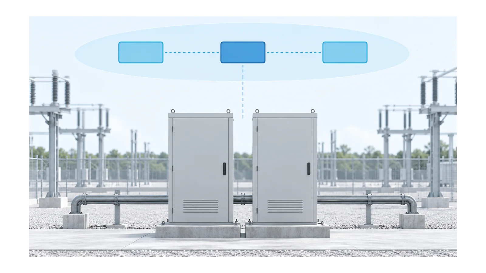
A substation single-line diagram (SLD) shows primary electrical connectivity; it is not a complete relay circuit. In an IEC 61850 installation, measurement samples and protection signals may travel over a communication network, but the network does not become the primary power path or the breaker trip-energy supply.
To understand one relay operation, trace five separate layers: primary power, measurement, protection logic, communication and physical actuation. Reconcile their equipment identifiers, then identify the drawing or configuration that proves each connection. This article explains that reading task, not relay settings, network design or a switching procedure.
What an SLD tells you—and what it leaves out
An SLD condenses a multiphase power system into a simplified drawing. It commonly identifies bus sections, transformers, breakers, disconnectors, feeders and instrument-transformer locations. Its legend, drawing conventions and revision define how much protection information is included.
Use it first to locate the protected primary circuit and every possible source. Determine which breaker separates which part of the circuit. A drawn breaker symbol does not prove the current position, the isolation state or which relay output operates its trip coil.
For equipment orientation, see distribution-substation fundamentals. The next step here is not another equipment list: it is following the information and actuation paths that make one protection function work.
Keep the five reading layers separate
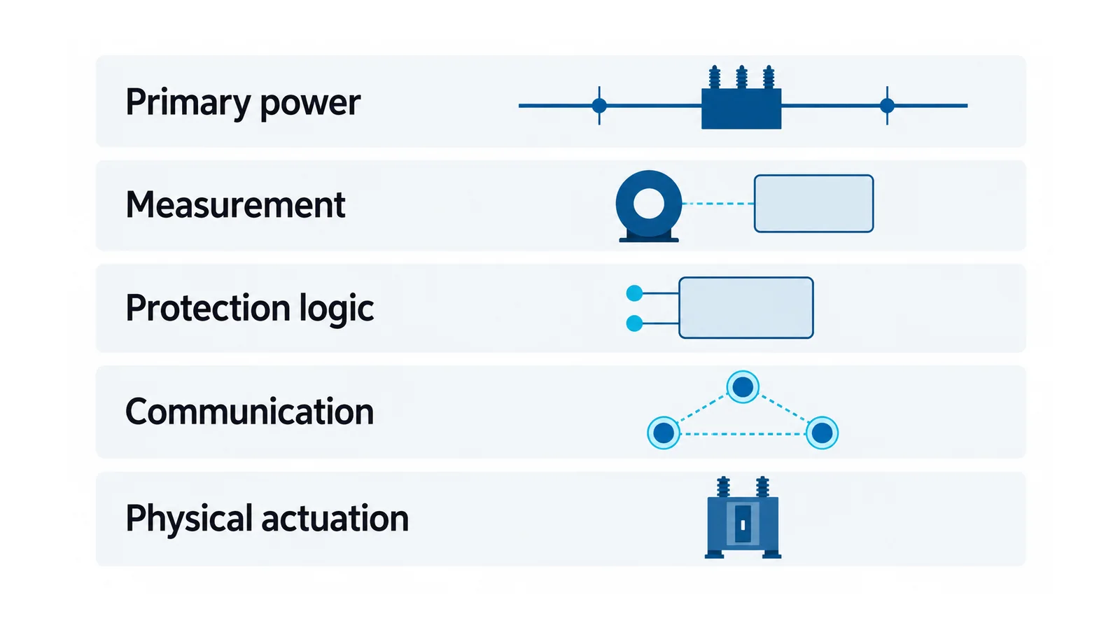
| Reading layer | Question to answer | Evidence to open next | Common mistaken inference |
|---|---|---|---|
| Primary power | Which circuit, source and breaker are involved? | SLD, protection-zone drawing and equipment schedule | A relay icon beside a breaker proves its trip wiring |
| Measurement | Which current/voltage is measured, and how does it reach the protection function? | CT/VT drawings, interface/merging-unit mapping and measurement configuration | A displayed current proves every protection input is correct |
| Protection logic | Which function decides to trip, block or alarm? | Approved relay logic/settings and function mapping | Every protection start is a trip command |
| Communication | Which device publishes data and which function consumes it? | Network drawings, signal register and deployed IEC 61850 configuration | Every Ethernet path carries the same kind of data |
| Physical actuation | How does the decision reach an interrupting device, with what trip supply? | Output mapping, DC schematic, trip-coil circuit and breaker evidence | A received message proves the fault current was interrupted |
The layers can be distributed across several devices, or several functions can reside in one intelligent electronic device (IED). They are a reading framework, not a required hardware arrangement.
Distinguish Sampled Values, GOOSE and station information
Sampled Values (SV) carry sampled measurements. A digital instrument-transformer interface or an appropriate merging unit supplies measurement data to consuming functions. IEC 61850-9-2:2011+AMD1:2020 defines the communication mapping for SV transmission. IEC 61869-9:2016 addresses the digital interface for instrument-transformer measurements.
GOOSE provides an event-oriented publisher/subscriber service used for signals such as protection trips, blocking and interlocking. It is not a stream of waveform samples. MMS supports client/server exchanges, including station-level information and controls in applicable implementations. IEC 61850-8-1:2011+AMD1:2020 describes the MMS and Ethernet mappings; the IEC TC57 protocol-stack overview hosted by IEEE visually separates these services.
“Process bus” generally identifies communication involving process-level measurements and equipment interfaces; “station bus” identifies station/bay communication roles. These labels do not prove that a particular project uses separate physical networks, or that all trip signals must be digital. Read the actual architecture.
Do not infer a sample rate, synchronization profile, latency budget or redundant topology simply from “IEC 61850.” Those are implementation and application questions requiring their own declared basis.
Trace one hypothetical feeder bay
The following identifiers describe an educational example, not an installed project or a relay-configuration recipe. Let feeder F01 have breaker Q01, current-transformer set CT01, merging unit MU01, protection IED P01 and a separate breaker-interface IED B01.
1. Locate the measured primary current
Find CT01 on the SLD and identify its relationship to Q01 and the protected circuit. Open the instrument-transformer documentation to determine which actual core/interface and conductor polarity feed the protection path. A separate metering core or station measurement is not automatically the protection input.
The CT and VT selection guide covers ratio, accuracy and burden considerations. A digital interface does not remove the need to establish a valid measurement source.
2. Follow the measurement into the relay function
In this example, CT01 measurements enter MU01, which publishes the configured SV stream consumed by P01. Confirm phase/channel mapping, scaling, the selected implementation profile and relevant quality/time handling. Compare the actual deployed configuration with the approved measurement mapping.
Do not treat every stream from MU01 as interchangeable. A relay subscribing to a valid Ethernet stream can still receive the wrong bay, phase or scaling. Where a function combines measurements from different sources, determine the required alignment and its behavior when trustworthy measurement/time information is unavailable.
3. Locate the protection decision and its digital destination
P01 applies the approved protection function to its inputs. In this example, its trip decision is published in a GOOSE dataset and consumed by the designated logic in B01. Identify the exact source data item and receiving function, not merely an arrow labeled “GOOSE.”
Confirm whether the signal represents a trip, a start, a block or a permissive. A publisher may distribute several data items to several consumers. The protection drawing must explain why this consumer is the correct destination and what conditions permit its action.
4. Close the physical trip path
B01’s mapped output operates the engineered trip circuit for Q01. Follow the relevant DC supply, protection, output contact/interface, trip coil and associated supervision on the actual schematic. The digital message provides information; the trip supply provides the electrical energy for actuation.
A different project might use P01’s hardwired output directly. Either arrangement must be traced from the decision to the physical interface. The substation trip-circuit checklist addresses this DC-to-coil task separately.
5. Separate commanded state from proven interruption
An event report that says “trip sent,” an output changing state, a breaker auxiliary indication and fault-current interruption are different observations. Record which one a drawing, log or test establishes. For multiple-source arrangements, identify every breaker or other device needed to remove the relevant contributions.
This distinction is central to breaker-trip event investigation. Do not reconstruct an entire physical operation from one communication timestamp.
Reconcile drawings with configuration—not names alone
An equipment label in an SLD, an IED name in a network drawing and a data reference in a configuration file need an explicit cross-reference. Similar names are convenient, but do not prove electrical or logical correspondence.
IEC 61850-6:2009+AMD1:2018+AMD2:2024 defines a configuration-description format covering IEDs, communication systems, switchyard functions and their relationships. Its System Configuration description Language (SCL) supports this engineering exchange. It does not eliminate the primary drawings or the physical trip schematic.
For one traced function, retain a compact record with:
- primary circuit and protected-zone identifiers;
- measurement source, channel mapping and consuming function;
- trip decision and approved logic revision;
- publisher, data item, consumer and communication path where used;
- output/interface, trip-supply drawing and interrupting device;
- drawing, configuration and evidence revisions that agree with each other.
If a relationship exists only in an engineer’s assumption, mark it unresolved. If the deployed configuration differs from the approved record, resolve the discrepancy before treating the path as verified.
What a complete reading can—and cannot—establish
A complete drawing trace identifies the intended path and the documents supporting it. It does not prove actual sensor accuracy, communication performance, relay behavior or breaker operation. Those require appropriately scoped evidence and authorized testing.
Reading an SLD is not an isolation clearance. Physical inspection, CT-secondary work, trip testing and switching require qualified personnel, an approved safety/test plan and applicable isolation controls. Do not disconnect a CT secondary, inject a message into an operating network or issue a breaker command to “see whether the drawing is right.”
The practical end state is simple: you can explain where a protection function gets its measurements, how it communicates its decision, and what physically interrupts the circuit—without confusing any of those layers.
Sources
- IEC 61850-9-2:2011+AMD1:2020: sampled-value communication mapping.
- IEC 61869-9:2016: instrument-transformer digital-interface scope.
- IEC 61850-8-1:2011+AMD1:2020: MMS and Ethernet communication mappings.
- IEC 61850-6:2009+AMD1:2018+AMD2:2024: configuration-description scope.
- IEC TC57 protocol-stack overview, November 2019: service-layer explanation, not a current application profile.