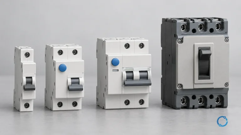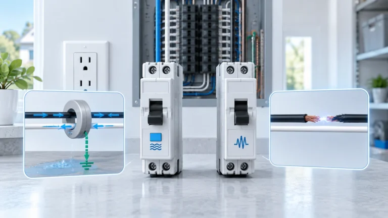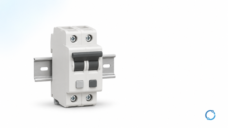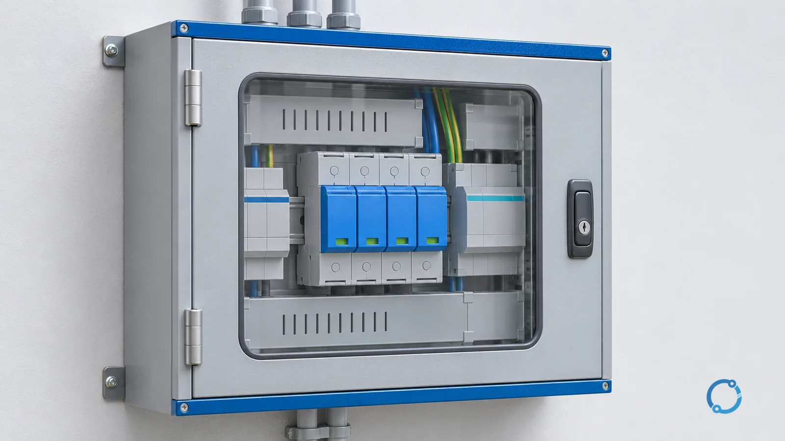
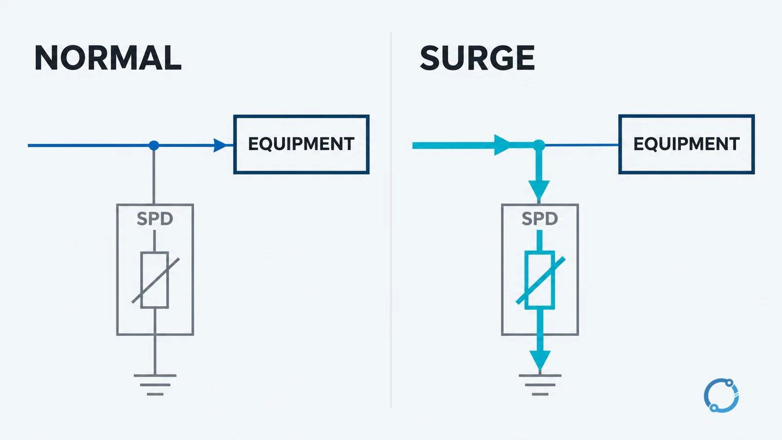
Short answer: A surge protective device (SPD) is a protective device that responds to a transient overvoltage by providing a controlled path for surge current and by limiting the voltage presented to downstream equipment. It is not a circuit breaker or fuse. A breaker or fuse interrupts a power-frequency overcurrent path; an SPD is designed to limit a short-duration voltage event, often while the rest of the installation remains in service.
That distinction is simple, but an SPD is not a magic barrier that absorbs every surge. Its performance depends on the device’s declared characteristics, the protection mode, the installation location, the connecting path and the coordination of the complete protection scheme. This article explains the device, the common component technologies and the meaning of Type 1, Type 2 and Type 3 classes without turning a type label into a universal installation rule.
Scope: an installed SPD, not a power strip label
In everyday shopping language, “surge protector” can mean a power strip with a few outlets. In electrical engineering, SPD is the more precise term for a device intended to limit transient overvoltages on a power circuit. The IEC 61643-11:2025 public scope describes low-voltage surge protective devices connected to AC power circuits and equipment, and notes that such devices contain at least one nonlinear component and are intended to limit surge voltages and divert surge currents. The standard’s scope is a useful identity boundary; it does not prove that a particular product is certified, suitable for a given installation or compliant with a local code.
This article uses low-voltage AC examples. The same broad idea appears in DC systems, signal circuits and photovoltaic installations, but the device ratings, protection modes, fault behavior and applicable standards can differ. For the basic distinction between the two current forms, see AC vs DC current.
SPD versus breaker and fuse
An overcurrent protective device and an SPD answer different questions.
A circuit breaker or fuse is selected to carry normal load current and to interrupt a fault current within its rating and time-current characteristics. It protects conductors and equipment against overload and short-circuit conditions. An SPD is selected to change the voltage across protected equipment during a transient event by diverting surge current through a controlled path. It may have an internal or external disconnector, and the manufacturer may specify backup protection, but those details do not turn the SPD into a general-purpose branch-circuit breaker.
This is why an SPD should not be used to justify removing a breaker, fuse or equipment grounding conductor. Protection against power-frequency faults still has to be designed, installed and verified separately.
Where surges come from
A transient overvoltage can be produced by a lightning-related event or by switching in the electrical system. Lightning does not have to strike the building directly to create a surge. A nearby strike can couple energy into conductors and create a fast voltage transient. Switching of capacitors, motors, transformers or other equipment can also produce temporary voltage changes, although the shape and energy of the event depend on the circuit.
The source matters because it affects the expected event and the coordination problem. A device that is appropriate for one location is not automatically appropriate at another. The installation should be designed around the actual supply, earthing arrangement and surge exposure rather than around a generic claim that one SPD “stops all surges.”
How an SPD limits voltage
Many AC SPDs use metal-oxide varistors (MOVs) as the nonlinear element. Under normal operating voltage, the MOV is intended to present a high resistance path so that it does not behave like a short circuit across the supply. When the voltage rises above the device’s intended operating region, its effective resistance falls and the device conducts a larger current. The current is diverted through the SPD and its connecting path instead of being imposed on the protected equipment.
The word “clamp” is useful, but it should not imply an ideal constant-voltage limiter. The voltage across the SPD changes with current and with the device’s construction. The residual voltage at the protected equipment also includes voltage developed across the connecting conductors. A short, direct and well-arranged connection is therefore part of the protection performance, not a cosmetic installation detail.
MOV and GDT in the same device
A gas discharge tube (GDT) is another nonlinear component that can be used in surge protection. It may be applied as a second stage or as part of a coordinated design, depending on the product and the system. A GDT can provide a path for a high-energy transient, while an MOV may provide a different limiting characteristic. The two technologies are not interchangeable, and this article does not assign a universal coordination arrangement.
The important reader takeaway is that component names alone do not establish performance. The complete device’s declared test basis and the way it is installed determine what the designer can claim.
Protection modes: L-N, L-PE and N-PE
An SPD can be connected between different conductors. The common shorthand labels describe those connections:
- L-N: protection between a line conductor and the neutral conductor.
- L-PE: protection between a line conductor and the protective earth conductor.
- N-PE: protection between the neutral conductor and the protective earth conductor.
These modes are not equivalent. The voltage across each pair, the fault behavior and the relevance of a mode depend on the supply and earthing arrangement. A device may provide one mode, several modes or a combination of internal connections, and the actual product diagram and installation instructions control what is permitted.
For a low-voltage installation, the SPD selection should follow the actual TN, TT or IT arrangement at the connection point. The dedicated SPD selection guide for TN, TT and IT earthing systems develops those checks. This article stops at the conceptual reason for multiple modes: a transient can appear between different conductors, so the protection designer must know which conductor pairs are being limited.
What Type 1, Type 2 and Type 3 mean
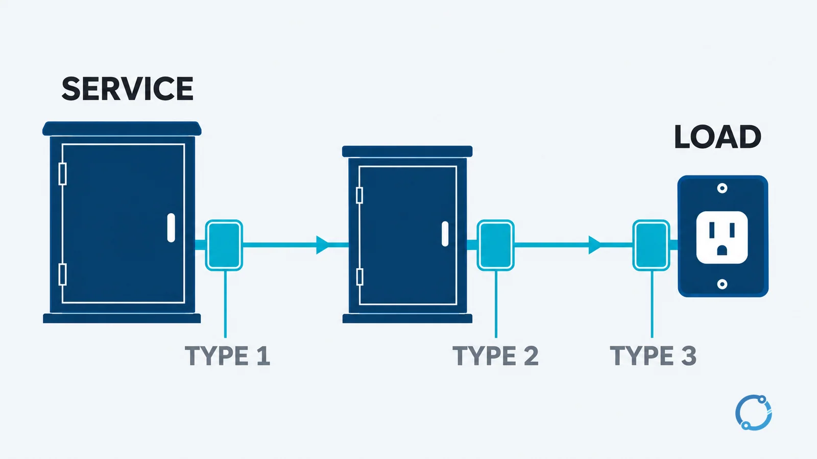
The Type 1, Type 2 and Type 3 labels describe intended installation positions and device classes within the relevant standard framework. The UL 1449 scope summary provides a useful public orientation: Type 1 devices are associated with the service-entrance side and main service equipment location; Type 2 devices are associated with the load side of the service equipment overcurrent device, including branch panels; and Type 3 devices are point-of-utilization devices.
Those statements should be read as a map, not a complete recipe. The exact permitted location, overcurrent protection and installation method depend on the product listing, the adopted code and the system design. A Type 1 label does not by itself prove that a device is suitable for every service entrance. A Type 3 label does not mean that an outlet protector can substitute for upstream protection.
The classes also should not be treated as a simple “bigger number is better” ranking. A Type 1 device, a Type 2 device and a Type 3 device can have different roles in a coordinated scheme. Cascading is the idea that multiple SPDs may be placed at different points so that each handles the part of the surge appropriate to its location. Coordination is a system decision; adding another device without checking its voltage, current and connection characteristics can change the result rather than improve it.
For transformer protection and medium-voltage boundaries, the selection questions are different again. The surge arrester selection article for transformer protection covers that adjacent problem. This page remains focused on explaining the low-voltage SPD’s role.
The parameters readers see on an SPD
Product literature commonly uses short parameter names. They are easy to confuse because they describe different parts of the device’s behavior.
Uc or MCOV: maximum continuous operating voltage
The maximum continuous operating voltage, often shown as Uc or MCOV, describes the highest continuous voltage the SPD is intended to withstand in its normal connected state. It must be selected for the actual system voltage and conditions, not for a transient rating. A higher number is not automatically better; the device also has to remain compatible with the system’s earthing and protection arrangement.
Up: voltage protection level
Up is a declared voltage protection level measured under the standard’s specified test conditions. It describes the residual voltage the device is intended to present to the protected circuit at a defined test current. The value is useful for coordination, but it is not a promise that the equipment will never see a higher voltage. Connection impedance, surge current sharing and the complete installation affect the voltage at the equipment terminals.
In: nominal discharge current
In is a nominal discharge current used to describe the device’s tested surge-current capability. It is not the normal load current, and it is not a statement that the SPD can carry the installation’s prospective short-circuit current. Those are different concepts and must be checked separately.
Imax: maximum discharge current
Imax is a maximum discharge-current parameter declared under the product’s test basis. It should be read with the waveform, test conditions and standard edition in the manufacturer’s documentation. A larger headline number does not prove better protection if the device’s Uc, Up, connection mode or coordination is wrong for the installation.
A bounded coordination calculation
Consider a stated example. A 230 V system supplies equipment whose rated impulse withstand voltage is 2.5 kV for its overvoltage category. An SPD at the relevant location has a declared Up of 1.5 kV.
The simple voltage margin is:
2.5 kV - 1.5 kV = 1.0 kV
Under the stated assumptions, the SPD’s protection level is 1.0 kV below the equipment’s withstand value. That is a useful first check, not a complete insulation-coordination study. The designer still has to account for the voltage across connecting conductors, tolerances, the actual surge current, the equipment’s overvoltage category and the applicable installation rules. The public scope of IEC 60664-1:2020 shows why insulation coordination is a system topic rather than a single product number.
The example also illustrates a useful habit: write down the two quantities being compared and their units. A lower Up can be beneficial when the rest of the scheme supports it, but “lower” alone is not a universal selection rule.
Status indication, degradation and replacement
An SPD can include a status indicator, a remote contact or another monitoring provision. The meaning of that indication is product-specific. A particular manufacturer may use a window, flag, label or signal in a defined way, but there is no universal color code that can be copied from one product to another. Read the instructions supplied with the actual device and follow the installation’s maintenance procedure.
An SPD may also degrade after repeated surge events or after a severe event. The product documentation should define the relevant condition and the permitted response. This article does not assign a replacement interval or a test that every reader can perform on an energized panel. Isolation, testing and replacement work should be planned by a qualified person under the applicable safety rules.
Common misconceptions
“An SPD blocks every surge”
An SPD limits transient voltage within its tested and installed capability. It does not eliminate every possible disturbance, and it cannot compensate for an inadequate earthing path, a poor connection or an unsuitable device selection. Protection is a system property.
“One SPD at the service entrance protects every load”
An upstream device can reduce the surge exposure of downstream equipment, but the voltage at a distant load can still be affected by the connecting path and by additional transient sources inside the installation. Whether additional coordinated protection is needed depends on the system, the equipment and the applicable standards.
“An SPD is a breaker, fuse or substitute for one”
The SPD’s normal job is transient voltage limiting. It is not the branch-circuit overcurrent protection, and it does not remove the need for short-circuit and overload protection. Its own failure behavior and any required disconnection or backup protection must be addressed in the product and installation design.
What to check before selecting an SPD
At a high level, the selection process starts with the installation, not the catalog:
- Identify the supply voltage, frequency and earthing arrangement at the SPD connection point.
- Determine which protection modes are available and required between line, neutral and protective earth.
- Confirm the equipment’s insulation-coordination and impulse-withstand requirements.
- Compare the SPD’s Uc, Up, In and Imax values with the actual system and the connected equipment.
- Check the intended Type 1, Type 2 or Type 3 location and the product’s installation instructions.
- Review the connecting conductors, disconnector or backup protection, status indication and fault behavior.
- Coordinate any multiple SPDs as one scheme, then verify the final installation against the locally adopted code.
The IEC 61643-12:2020 public scope describes selection, operation, location and coordination as application principles for low-voltage SPDs. That is the right level at which to think about the problem: an SPD is a component in a protection plan, not a standalone guarantee.
FAQ
What is a surge protector (SPD) in simple terms?
An SPD is a device that limits a short-duration overvoltage by diverting surge current and reducing the voltage seen by downstream equipment. It is not the same as a circuit breaker or fuse, which provides overcurrent protection.
What is the difference between Type 1, Type 2 and Type 3 SPDs?
The types describe different intended installation positions and device classes. In broad terms, Type 1 is associated with the service entrance, Type 2 with distribution or branch-panel locations on the load side of service equipment, and Type 3 with point-of-use protection. The exact application still depends on the product listing, installation instructions and adopted code.
Does an SPD replace a circuit breaker or fuse?
No. A breaker or fuse interrupts overcurrent, while an SPD limits transient overvoltage. The installation still needs appropriate overcurrent protection, earthing and fault protection, and the SPD may have its own disconnector or backup-protection requirements.
What do L-N, L-PE and N-PE protection modes mean?
They describe which conductor pairs an SPD protects: line to neutral, line to protective earth, and neutral to protective earth. The relevant modes depend on the supply and earthing arrangement, and not every device provides every combination.
Is a lower Up always the best SPD choice?
No. Up is one input to insulation coordination. The device must also match the system voltage, protection mode, installation location, surge-current requirements and coordination with other protective devices. A lower value can be useful only when the complete scheme supports it.