
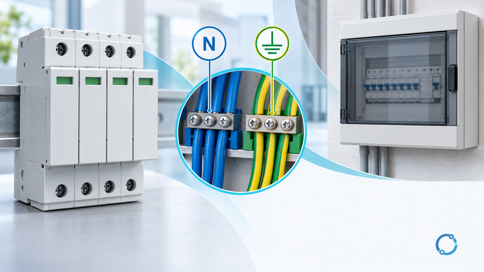
Select a surge protective device from the earthing arrangement at its actual connection point, not from the supply voltage alone. Identify the available conductors, the voltage between each proposed protection mode, and how a failed SPD will be disconnected. Then verify temporary-overvoltage duty, RCD interaction and installed connection geometry. A drawing suitable downstream of a PEN split is not automatically suitable upstream of it.
This guide concerns low-voltage AC installations. It does not cover medium-voltage surge arresters, photovoltaic DC SPDs or a universal wiring diagram. IEC 61643-12:2020 addresses LV AC SPD selection and application. Installation requirements belong to the locally adopted rules, with IEC 60364-5-53, consolidated through Amendment 2:2024 providing the international device-selection framework. These public catalog pages establish scope, not access to every normative clause.
Establish the conductor boundary first
Record whether neutral and protective functions are separate or combined where the SPD will be installed. In TN-S they are separate. In a TN-C portion a PEN conductor combines them. A TN-C-S supply has a separation boundary, so the applicable arrangement depends on which side of that boundary the device occupies. Do not create an additional neutral-to-PE bond merely to copy an SPD drawing.
In TT systems, the installation protective earth uses its local earthing arrangement rather than relying on a supplied TN protective conductor. In IT systems, the source is isolated from earth or connected through an impedance. The first earth-fault condition is therefore an important design state, not merely an abnormal event to ignore. Have the designer confirm the actual arrangement, including alternate supply and islanded modes.
IET’s explanation of TN, TT and IT arrangements provides terminology context in its “IT systems in railways” article. Use it for the concepts, not as a current installation-rule checklist.
Use this as an input and rejection matrix, not an instruction to connect particular terminals:
| Installation condition | Establish before selecting the SPD | Reject or hold when |
|---|---|---|
| TN-S, or TN-C-S downstream of the split | Separate N and PE, protection modes and permitted bonding arrangement | The proposed device assumes a PEN connection or requires an unauthorized N–PE link |
| TN-C section | Actual PEN boundary and an explicitly suitable connection arrangement | A separate PE or N is assumed where neither exists independently |
| TT | SPD connection arrangement, position relative to RCDs and fault-disconnection path | A failed SPD could leave a dangerous conductive path without verified disconnection |
| IT | Neutral availability, first-fault conductor-to-earth voltages and monitoring compatibility | Continuous/TOV duty is checked only for the normal balanced state |
| Multiple sources or operating modes | Earthing and bonding in every permitted configuration | One SPD arrangement is justified using only the normal utility-supplied state |
The earthing label is only the start. Retain the one-line diagram, bonding boundary and approved device instructions together. A designation on a schedule cannot resolve an undocumented site conversion.
Build a mode-by-mode voltage register
For each proposed mode, such as line-to-neutral, line-to-PE or neutral-to-PE, record the normal maximum voltage and credible temporary overvoltages. Match those conditions to the device’s maximum continuous operating voltage and documented TOV behavior. Do not select by a low protection-level number alone: a device must remain suitable for the supply conditions it will actually experience.
Next compare the protection level with the protected equipment’s impulse withstand, allowing for the installation and any additional coordinated devices. Document the lightning exposure, supply entry and protection objective that justify the relevant SPD test classification. IEC and North American device classifications use different frameworks; a familiar type number is not enough to establish equivalence.
The useful output is a register with one row per mode: conductor pair, maximum continuous exposure, TOV case, applicable device evidence and protected-equipment requirement. Leave unresolved fields visibly open. A generic “three-phase SPD” description conceals too much of this decision.
Make failure disconnection and RCD interaction explicit
An SPD installation must address the device’s failure condition as well as a successful surge event. Verify prospective fault current, the specified internal or external disconnector, permitted backup protection and the connecting conductors. If a separate protective device is omitted, retain the evidence that permits omission for that exact arrangement. An internal thermal disconnector is not automatically proof of every short-circuit duty.
IET’s April 2026 technical guidance on SPD overcurrent protection explains why a dedicated OCPD is not required in every arrangement, while retaining coordination and fault-protection conditions. It also discusses TT arrangements relative to RCD protection. Apply its UK context carefully; it is not a universal permission to rely on a supply fuse.
For a TT installation, specifically review whether the proposed SPD arrangement preserves shock protection if an element fails. Where an RCD is involved, check its location, surge behavior and coordination against the adopted installation rules and device documentation. Moving an SPD to avoid nuisance RCD operation can change the fault-protection boundary.
The ordinary circuit-breaker sizing workflow helps separate load, conductor and fault duties. SPD backup protection still needs the exact SPD/protective-device evidence; an ampere rating alone does not establish that combination.
Review the installed loop, not just the device label
The connecting path contributes to the voltage seen by equipment during a surge. NIST’s research on SPD lead arrangements shows why lead dress and coupling matter alongside length. Route connections to avoid unnecessary loop area and separation, following the approved arrangement. Increasing conductor cross-section alone does not eliminate the geometry problem.
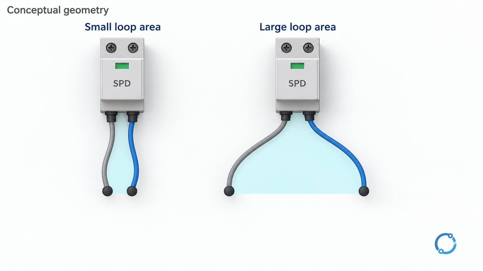
Do not extract a universal volts-per-metre allowance from a simplified drawing. Use the applicable rules and installation evidence, including routing constraints inside the assembly. Confirm that inspection, replacement and status indication remain accessible without compromising electrical separation.
Close the acceptance record safely
Before release, the responsible designer and qualified installer should confirm:
- The actual earthing arrangement and all permitted source configurations match the selection record.
- Protection modes, continuous voltage, TOV behavior and equipment withstand are documented.
- Fault rating, backup protection, RCD interfaces and conductor requirements match the approved arrangement.
- Installed routing, connections, bonding and status indication have been checked.
- Isolation, replacement and post-event inspection responsibilities are assigned.
Any associated work requires isolation from every relevant source, verification of the safe state and control of stored energy under the site procedure. For testing, use the insulation-resistance testing guide to define the test boundary; connected SPDs and electronics may require exclusion under their instructions. Record their restoration before energization.
Sources
- IEC 61643-12:2020 — LV AC SPD application scope
- IEC 60364-5-53:2019+A1:2020+A2:2024 — device-selection and installation framework
- IET Wiring Matters, Summer 2014 — earthing terminology in “IT systems in railways”
- IET — SPD overcurrent protection, April 2026
- NIST — lead-length and connection-arrangement research