
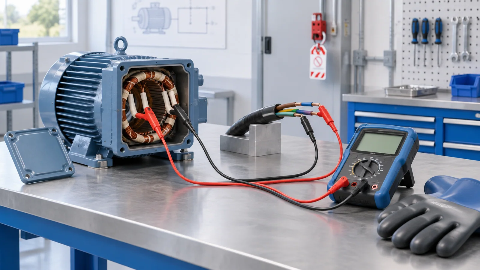
Insulation resistance testing applies a controlled DC test voltage to de-energized insulation and measures the small current that flows. The instrument reports resistance, usually in megohms or gigohms. The result can reveal moisture, contamination, deterioration or installation damage, but a single number is not a diagnosis and there is no universal “good megohm” value for every cable, motor and installation.
A defensible result records the asset, circuit boundaries, test voltage, duration, temperature, humidity, connection method and prior history. Acceptance criteria must come from the governing standard, equipment instructions, commissioning specification or an engineering assessment appropriate to that asset.
What the test actually measures
The basic relationship is:
R = V / I
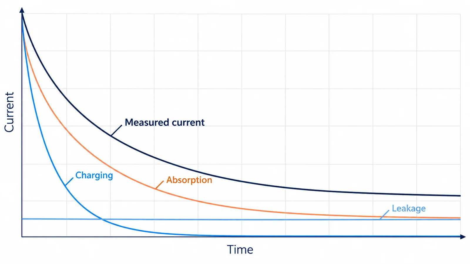
The current measured immediately after DC voltage is applied is not one pure leakage current. It is a changing combination of:
- Capacitive charging current, initially high and normally decaying quickly as the asset charges.
- Dielectric absorption current, which decays more slowly as polarization develops within the insulation system.
- Surface leakage current, influenced by moisture, dust, salts, oil and the geometry of exposed insulating surfaces.
- Volume conduction current, the more stable current through the insulation body.
Because these components change with time, a reading at 15 seconds cannot be compared directly with a reading at 60 seconds unless the procedure intentionally uses those intervals. Long cables, large windings and equipment with filters or surge components may take longer to charge and can retain hazardous energy after the test.
What insulation resistance can and cannot tell you
An insulation resistance test is useful for:
- verifying installation condition before energization when required by the applicable standard;
- establishing a commissioning baseline;
- finding gross contamination, moisture ingress or damaged insulation;
- comparing phases, conductors or similar assets under comparable conditions;
- trending deterioration during planned maintenance;
- supporting—but not replacing—a broader diagnostic program.
It does not by itself prove:
- that insulation can withstand every operating or transient voltage;
- that partial discharge is absent;
- that a cable termination, winding or connector has no localized defect;
- that protective devices and grounding are correct;
- that an asset is safe to energize under all service conditions;
- that a low reading identifies the exact failure location.
Other tests may be needed, such as continuity, protective-conductor verification, dielectric withstand testing, polarization/depolarization measurements, dissipation factor, partial discharge, surge testing, winding resistance or offline cable diagnostics. Those tests answer different questions and can impose different electrical stress.
Standards and equipment scope
IEC 61557-2:2019 specifies requirements for equipment used to measure insulation resistance in de-energized low-voltage equipment and installations up to 1,000 V AC and 1,500 V DC. It governs the measuring equipment within its scope, not a universal acceptance value for every asset.
IEC 60364-6:2016 covers initial and periodic verification of low-voltage electrical installations. At the time of this review in September 2026, IEC also listed IEC 60364-6:2026 as a pre-release version. Projects should verify the final published edition, local adoption and national deviations before applying requirements.
Rotating machines have their own context. The IEEE P43 project page describes an active revision project that will supersede IEEE 43-2013 and identifies the scope as armature and field windings of rotating machines rated 750 W or greater. A motor-winding criterion should therefore not be transferred to building wiring or electronic equipment.
Safety boundary before connecting a tester
An insulation resistance tester is a high-voltage source even when the asset is isolated from normal supply. Testing must be performed by qualified personnel under an approved procedure.
Before testing:
- Identify every source, backfeed path and connected energy-storage element.
- De-energize, isolate, lock and tag according to the applicable procedure.
- Have a qualified person verify absence of voltage with suitable test equipment.
- Disconnect or protect components that could be damaged by the DC test voltage, including sensitive electronics, surge protective devices, variable-frequency drives, power supplies, meters and control equipment where required.
- Establish a controlled test area and prevent contact with conductors under test.
- Confirm the tester, leads, probes, measurement category and voltage rating suit the task.
- Plan discharge and grounding before the test begins.
In the United States, OSHA 1910.333 generally requires exposed live parts to be de-energized before work unless a stated exception applies. Verification of de-energization is itself performed by a qualified person. The equipment under insulation test must be treated as energized while the tester is applying voltage and until stored energy has been safely discharged.
Building a valid test plan
Define the test object and boundaries
Record exactly what is included: conductor-to-conductor, conductor-to-earth, winding-to-frame, all phases tied together, individual phases, cable plus connected load, or another configuration. A changed boundary can change the result more than the insulation condition does.
Select test voltage from the governing document
Test voltage depends on rated voltage, insulation system, asset type, connected devices and the purpose of the test. Do not choose a voltage from a generic internet table. Use the applicable installation or product standard, equipment instructions and approved test specification.
Standardize duration
Common programs record a fixed-time reading, often after a defined interval. Rotating-machine procedures may also use timed ratios. The selected duration must be long enough for the intended method and applied consistently across trend records.
Record environmental conditions
Insulation resistance is strongly affected by temperature and surface condition. Moisture and contamination can lower readings. Temperature correction may be appropriate for a specified insulation system, but the correction relationship must come from a suitable standard or engineering source. Corrected and uncorrected values should both remain traceable.
Control the connection method
Use clean, secure leads and a repeatable connection arrangement. A guard terminal, where the instrument and procedure support it, can divert unwanted surface leakage away from the measuring circuit. Guarding does not repair poor insulation; it helps separate a defined current path from surface leakage.
A bounded testing sequence
This sequence describes quality gates, not a substitute for an employer’s procedure:
- Review the asset data, previous results, test specification and drawings.
- Isolate and prove de-energized using the approved safe-work process.
- Separate incompatible components and document every temporary disconnection.
- Inspect for moisture, dirt, carbon tracking, damaged insulation and loose test connections.
- Connect the tester with the circuit discharged and grounded as required.
- Apply the specified test voltage for the specified duration without touching the test circuit.
- Record resistance versus time, test voltage, ambient and asset temperature, humidity, configuration and instrument identity.
- Discharge the asset using the tester’s designed discharge function and the approved grounding process. Confirm it is safe before contact.
- Restore all temporary connections, protective devices, bonds and covers using documented checks.
- Interpret the result against asset-specific criteria and comparable history.
PI and DAR: useful ratios with limits
Timed resistance ratios describe how the reading rises during a test:
Polarization Index (PI) = R at 10 minutes / R at 1 minute
Dielectric Absorption Ratio (DAR) = resistance at the later specified time / resistance at the earlier specified time
Exact DAR intervals vary by procedure. These ratios can reduce the influence of absolute scale and help characterize some insulation systems, especially rotating-machine windings. They are not universal condition scores.
PI or DAR may be misleading when:
- the asset has low capacitance and reaches a stable reading quickly;
- the instrument reaches its measurement limit;
- modern insulation has very low leakage;
- temperature changes during the test;
- contamination creates unstable surface current;
- connected devices alter the current;
- the winding or cable is too short for the ratio to be diagnostic;
- the applicable standard does not use that ratio for the asset.
How to interpret results
| Observation | Possible explanation | Next engineering action |
|---|---|---|
| Similar to corrected historical trend | Condition may be stable | Confirm test comparability and continue the approved program |
| Lower than history on all phases | Moisture, temperature difference, changed boundary, contamination or broad deterioration | Verify conditions, connections and correction method before diagnosing |
| One phase much lower | Local contamination, cable damage, winding defect or connected component | Isolate sections and escalate to asset-specific diagnostics |
| Reading rises steadily with time | Normal charging and absorption behavior may be present | Compare curve shape and timed ratio only with the applicable method |
| Reading fluctuates | Poor connection, intermittent discharge, contamination, electrical interference or unstable insulation | Stop if unsafe; verify setup and asset condition |
| Very high or over-range reading | Dry/clean insulation, short test object, open connection or instrument limit | Prove connection integrity; do not treat over-range as automatic proof of health |
| Sudden collapse during test | Breakdown, flashover, lead movement or component conduction | Stop, discharge and investigate before repeating |
The strongest interpretation usually combines three views:
- absolute criterion, where a governing document provides one;
- phase or peer comparison under the same conditions;
- trend over time with consistent voltage, duration, temperature treatment and boundaries.
Common causes of bad data
- Testing through connected electronic equipment.
- Comparing different test voltages or durations.
- Omitting temperature and humidity.
- Measuring dirty terminal surfaces without documenting their condition.
- Failing to discharge the cable or winding between repeated tests.
- Changing which conductors are tied together or grounded.
- Using damaged leads or an instrument outside calibration.
- Recording only the final megohm value without the time curve.
- Applying a motor-winding rule to a cable or building installation.
- Treating the highest reading as the best reading without proving the circuit was connected.
Minimum test record
Every retained result should identify:
- asset and circuit ID;
- test boundary and connection diagram;
- rated voltage and asset type;
- test voltage and duration;
- resistance at defined times;
- PI or DAR only when applicable;
- ambient and asset temperature, humidity and surface condition;
- instrument model/serial number and calibration status;
- disconnections, guards and temporary grounds;
- previous comparable result and acceptance basis;
- tester, reviewer and resulting action.
Bottom line
Insulation resistance testing is most valuable as a controlled, repeatable measurement—not as a hunt for one magic megohm number. Define the asset and standard, make the circuit safely de-energized, select an appropriate test voltage and duration, record environmental conditions, discharge the asset, and interpret the result using applicable criteria plus comparable history. When the data are inconsistent or the trend deteriorates, investigate the test setup and the insulation system before deciding whether the equipment can return to service.
References
- IEC 61557-2:2019 — Equipment for measuring insulation resistance
- IEC 60364-6:2016 — Verification of low-voltage electrical installations
- IEC 60364-6:2026 pre-release edition status
- IEEE P43 — Revision project and scope for rotating-machine insulation resistance testing
- OSHA 1910.333 — Selection and use of electrical work practices