
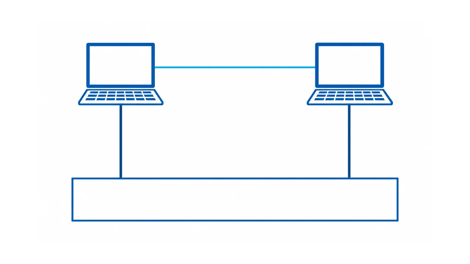
When a computer resets, a data link fails or connected equipment produces interference, keep the protective grounding path intact and investigate the power and data interfaces together. The symptom does not prove a grounding defect. Cutting a grounding pin, lifting protective earth or connecting equipment to a separate unbonded rod can introduce a safety problem without resolving the actual cause.
First separate an urgent electrical defect from an interference problem. Shock or tingling from accessible metal, visible damage, burning odor, or unexplained protective-device operation requires a controlled response through the site’s electrical-safety process. Stop using suspect equipment where appropriate and have qualified personnel assess it; do not continue experiments with its grounding connection.
This guide addresses building-supplied computers and connected information-technology equipment. U.S. general-industry provisions are identified where used; local electrical rules and the actual equipment construction remain decisive. It is not an outlet-rewiring procedure or a universal rule for data-cable shields.
Separate four different functions
| Term | Function in this discussion | Common mistaken inference |
|---|---|---|
| Protective earth (PE) or equipment grounding conductor (EGC) | The designed protective connection for exposed conductive parts where required | “It can be disconnected to remove noise.” |
| Neutral or grounded circuit conductor | A circuit conductor that may carry normal load current | “It is interchangeable with the equipment-grounding connection.” |
| Signal reference or shield | Part of a specified data/interface or interference-control design | “It always has the same connection rule as PE.” |
| Grounding electrode system | The building/system connection to earth under its applicable design | “A nearby rod alone supplies the required equipment fault-return path.” |
In an ordinary grounded building circuit, the protective path needs to return fault current through the designed supply/bonding arrangement. Soil should not be assumed to replace that conductor path. Do not add an arbitrary neutral-to-chassis connection at a workstation.
For covered U.S. installations, OSHA 1910.304 requires an effective, continuous grounding path and describes equipment-grounding conductor arrangements. It does not authorize a noise experiment that disconnects a required protective path.
Some equipment uses an approved construction that does not require an EGC, such as appropriately designed double-insulated equipment. Follow that equipment’s identified protection method. Absence of an earth pin on one approved device does not authorize removing the pin from another.
Map the power and data boundaries
List each connected device and its electrical supply: workstation, monitor, printer, network switch, powered peripheral, rack equipment and any uninterruptible power supply (UPS). Then add data, audio, video and shielded connections between them, including links to equipment elsewhere in the building.
Do not assume a UPS eliminates a grounding or interface problem. Its normal, bypass and battery operating states may have different relevant dependencies. Preserve the actual supply and bonding arrangement during any approved investigation.
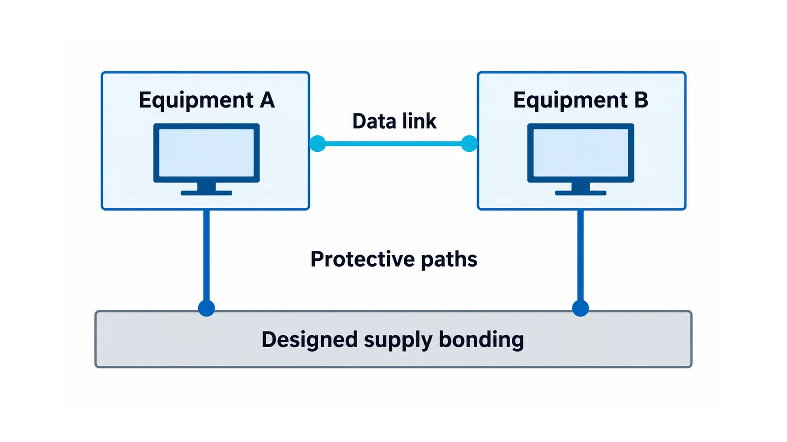
The National Institute of Standards and Technology’s historical paper Protecting computer systems against power transients, originally published in 1990, explains how interconnected power and data paths can expose electronics to different reference potentials during disturbances. That mechanism remains useful; the paper’s legacy interfaces and code references are not a current installation specification.
A data connection may create an additional conductive relationship, depending on the interface and shield/chassis design. Conversely, a suitable optical link can remove a particular conductive data path. Neither observation determines how the power protective conductor should be installed or permits its removal.
Use symptoms to choose evidence, not to name a fault
| Symptom or event | Credible possibilities | Evidence to seek | Safe next action |
|---|---|---|---|
| Reset when a large load starts | Voltage sag, power-supply response, UPS transfer or another disturbance | Timestamped event history and appropriately obtained power-quality records | Investigate supply behavior before changing grounding |
| Interference appears with a particular data/peripheral link | Interface reference, shielding, defective cable/device or coupling | Reproducible topology and equipment/interface documentation | Use approved substitution or interface review while preserving PE |
| Shock, tingling or suspect accessible-metal voltage | Insulation defect or protective-path problem among other causes | Qualified electrical inspection and suitable tests | Treat as a safety issue; do not try a ground-lift experiment |
| Residual-current protective device operates | Leakage, fault, incompatible installation or connected-load interaction | Device type, circuit records and qualified fault investigation | Do not bypass the protective device |
| Symptoms after moving a desk or adding equipment | Changed outlet, cord damage, new power/data path or loading | Before/after connection map and change record | Inspect the change and escalate electrical discrepancies |
This table lists hypotheses, not diagnoses. A reset can coincide with another event without sharing its cause. The voltage-sag and swell diagnostic guide owns disturbance classification; use it when the evidence points to the supply waveform rather than a grounding alteration.
Begin with observation and controlled substitutions
Record when the symptom occurs, which devices and links are connected, what operating state the UPS uses, and what changed recently. Retain logs with a consistent time basis. Note whether the event affects one device, a shared circuit or multiple linked systems.
Visually check accessible cords, plugs and equipment for damage without opening covers or exposing electrical parts. Users should not dismantle a receptacle or measure inside an energized panel to investigate a computer problem. A simple plug-in indication also cannot prove every aspect of grounding effectiveness or detect every wiring defect.
If the equipment instructions and site procedure permit it, substitute a known-suitable data cable, peripheral or power supply one item at a time. Disconnecting an ordinary data peripheral for a controlled test is different from disconnecting a safety conductor. Keep any functional-safety or process dependency in scope before changing industrial network connections.
Document what the substitution demonstrates. A symptom disappearing with one data link removed suggests that link or its connected equipment matters. It does not establish a broken PE conductor, prove a “ground loop,” or identify the correct permanent fix.
Have qualified personnel verify the electrical installation
An electrical assessment may need to verify supply connections, conductor identity, protective-path continuity and effectiveness, equipment condition, leakage and relevant power-quality behavior. The tests and acceptance criteria depend on the installation, equipment class and local rules.
For applicable U.S. general-industry electrical work, OSHA 1910.333 provides safe-work and qualified-person verification requirements. Measurements that require exposure to electrical parts belong within that controlled work, not an IT troubleshooting improvisation.
Do not infer safety from one resistance or voltage reading without its test setup and interpretation. A required fault-return path, a grounding electrode measurement and high-frequency interference behavior are different questions. A good earth-resistance number alone cannot validate a workstation’s complete equipment-grounding path.
The GFCI-versus-AFCI guide explains their different protective functions. A ground-fault circuit interrupter (GFCI) is not a general noise filter, and an arc-fault circuit interrupter (AFCI) does not diagnose a data-interface problem.
Specify a fix for the demonstrated mechanism
If the protective path or equipment insulation is defective, correct that safety defect using the approved electrical process. Do not substitute a shield, rack bolt or added rod as an undocumented protective conductor.
If electrical safety checks are satisfactory and the evidence identifies an interface problem, the engineering review can consider routing, shield/reference design, appropriate interface isolation, optical links or coordinated protection at the relevant interfaces. Select an arrangement supported by the actual equipment and network requirements.
An isolation transformer or an isolated-ground arrangement is a designed electrical installation, not a promise that equipment can operate without protective bonding. Have the applicable wiring, supply and protection requirements resolved by the responsible electrical designer. No universal instruction to ground only one end of every shield follows from the words “ground loop.”
Retain the symptom, connection map, test basis, observed results, approved correction and verification after the change. The investigation is complete when the documented mechanism is addressed and the required protective function remains intact. A quieter computer with an undocumented grounding alteration is not an acceptable resolution.