
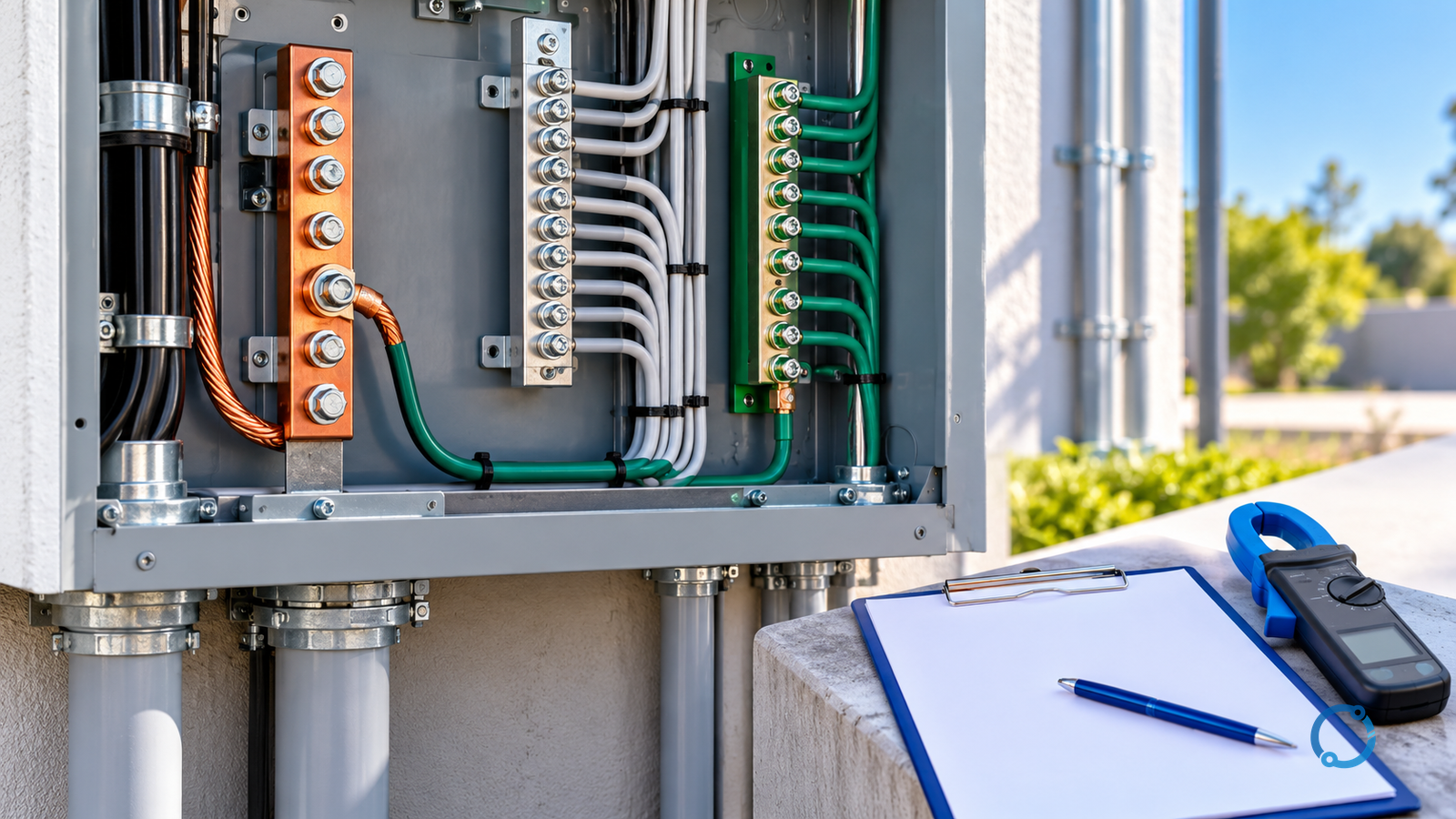
Current in a grounding or bonding conductor is evidence that a conductive path exists. It is not, by itself, evidence of a ground fault, a bad earth electrode or a dangerous equipment defect. The current may be normal neutral return current sharing an unintended route, fault current from insulation failure, circulating current between bonded systems, a rectified or DC component, or current produced by another source entirely.
The correct first response is therefore not to open the protective conductor to see what happens. That action can remove a fault-current path, create a touch-voltage hazard and make the test result meaningless. Preserve the bonding system, identify the electrical topology, and plan measurements that reveal where current enters, where it leaves and which conductors form the complete return circuit.
This workflow is written for qualified electrical engineers and test personnel. It does not provide live-testing instructions, a universal current threshold or a substitute for the adopted electrical code, the utility’s requirements and the site’s approved electrical safety program.
The short answer: locate the path before naming the fault
When a clamp meter shows current on a grounding conductor, record the observation without immediately interpreting it:
- Identify the conductor function and the system-earthing arrangement.
- Establish which normal return conductor should carry load current.
- Map every bonded metal path that could form a parallel circuit.
- Determine whether the current is steady, switched, intermittent or event-related.
- Compare current with voltage, load state and the protection system’s event history.
- Decide whether the condition is an installation defect, a fault, a normal but unwanted circulating path or an invalid measurement.
Only after those steps can anyone state whether the current is objectionable. Even then, the word does not create one numerical limit. The applicable installation rules, the reason current is using a non-current-carrying path, the possible touch and step voltages, conductor heating, electromagnetic effects and the risk of losing a protective path all matter.
Separate the conductor names from their jobs
Every conductor in the discussion must be identified by function rather than color alone.
| Conductor or path | Intended function | Diagnostic question |
|---|---|---|
| Phase or line conductor | Supply and load current | Is this the source whose current is being sought? |
| Neutral or mid-point conductor | Normal return current in a grounded system, where installed | Where should this current return, and is it actually doing so? |
| Protective earthing or equipment grounding conductor | Bond exposed metal and provide a fault-current path | Is it carrying only its intended fault or shield current? |
| Bonding jumper | Maintain electrical continuity between metal parts | Is the jumper part of an intended equipotential or fault path? |
| Earth electrode and earthing conductor | Connect a defined system point or electrode system to earth | Does current in this path explain the observed return circuit? |
| Cable sheath, tray, conduit, water pipe or building steel | Structural or shielding metal, sometimes bonded | Is it being used as an unintended parallel neutral? |
| Functional or signal ground | Provide a reference for electronics | Has it been connected to protective earth in a way the design does not support? |
Color codes and local terminology differ. A green-and-yellow conductor may be protective bonding in one installation, while another conductor plays a combined protective and functional role. Read the drawings and installation standard rather than inferring the circuit from a photograph.
The neutral earthing system selection guide explains how the system grounding arrangement changes fault-current paths. The main bonding jumper and equipment grounding conductor sizing pages define related design checks that must not be bypassed during troubleshooting.
Treat protective bonding as evidence, not as an experiment
The protective earthing and bonding system serves several functions. It establishes a low-impedance path for fault current in many system designs, limits voltage between accessible metal parts, and provides the path on which protective devices and touch-voltage management depend.
Opening one section of that path to insert a meter can:
- make exposed equipment live while a fault is present;
- transfer current to an unintended route;
- damage electronics connected to several bonded parts;
- disturb a parallel path whose low impedance is important for fault clearance;
- create a temporary condition that differs from every normal operating state;
- produce a current reading that describes the test connection more than the original installation.
For this reason, a diagnostic plan must begin with the safe-work method. Isolation, lockout/tagout, absence-of-voltage verification, temporary protective measures and the use of rated test accessories must be defined under the site procedure. In the United States, OSHA 29 CFR 1910.333 establishes electrical work-practice requirements. It does not authorize a diagnostic method that bypasses the applicable safe-work controls.
Measurements made while equipment is energized should be performed only by qualified persons using an approved procedure, suitable instruments and suitable personal protective equipment. A clamp meter’s convenience does not make an exposed conductor safe.
Gate 1: define the symptom and the operating state
“There is stray current” is not a complete symptom. Begin with a record that can be reproduced:
| Observation | Why it matters |
|---|---|
| Exact conductor and location | Current may be measured on a main bonding jumper, branch protective conductor, conduit, tray or electronic reference. These are different questions. |
| Source and feeder identity | A building with multiple supplies, generators, transformers and uninterruptible systems can have more than one intended return path. |
| Load state at the time | Current that appears only with a motor, heater, charger or VFD points toward a different circuit than current present with all normal loads off. |
| Current waveform | A clamp’s basic current mode may show a value while waveform shape remains unknown. |
| Frequency and stability | Steady 50/60 Hz current suggests a power-frequency path; pulsing or high-frequency current suggests a different mechanism. |
| Protective-device events | A trip, alarm or ground-fault indication can establish that the system saw an event the current observation has not explained. |
| Touch, shock, noise or heating complaints | These are separate hazards and must be handled through the applicable safety procedure, not dismissed because the clamp reading is small. |
| Recent work | Changed neutrals, added bonding, new drives, generators or electronic equipment can create a parallel or circulating path. |
Record instrument make and model, range, clamp jaw position, orientation, calibration status and the minimum resolution. A low-current reading near the instrument’s noise floor is not the same as a verified process current. For very low or complex currents, use an instrument and method appropriate to the expected frequency content and conductor geometry.
Gate 2: reconstruct the complete electrical topology
Before placing a meter, draw the system. A useful topology sketch includes:
- every source, including utility supply, transformers, generators, UPS outputs and separately derived systems;
- neutral and protective-earth connections;
- main bonding jumpers and equipment bonding jumpers;
- feeder and branch protective conductors;
- switchgear frames, panel enclosures, cable trays, conduit and building steel;
- process pipes, structural steel and any intentionally bonded extraneous conductive parts;
- surge-protective devices, filters and equipment designed to divert transient current;
- normal load-return paths and every known parallel path;
- isolation points, ties and transfer arrangements.
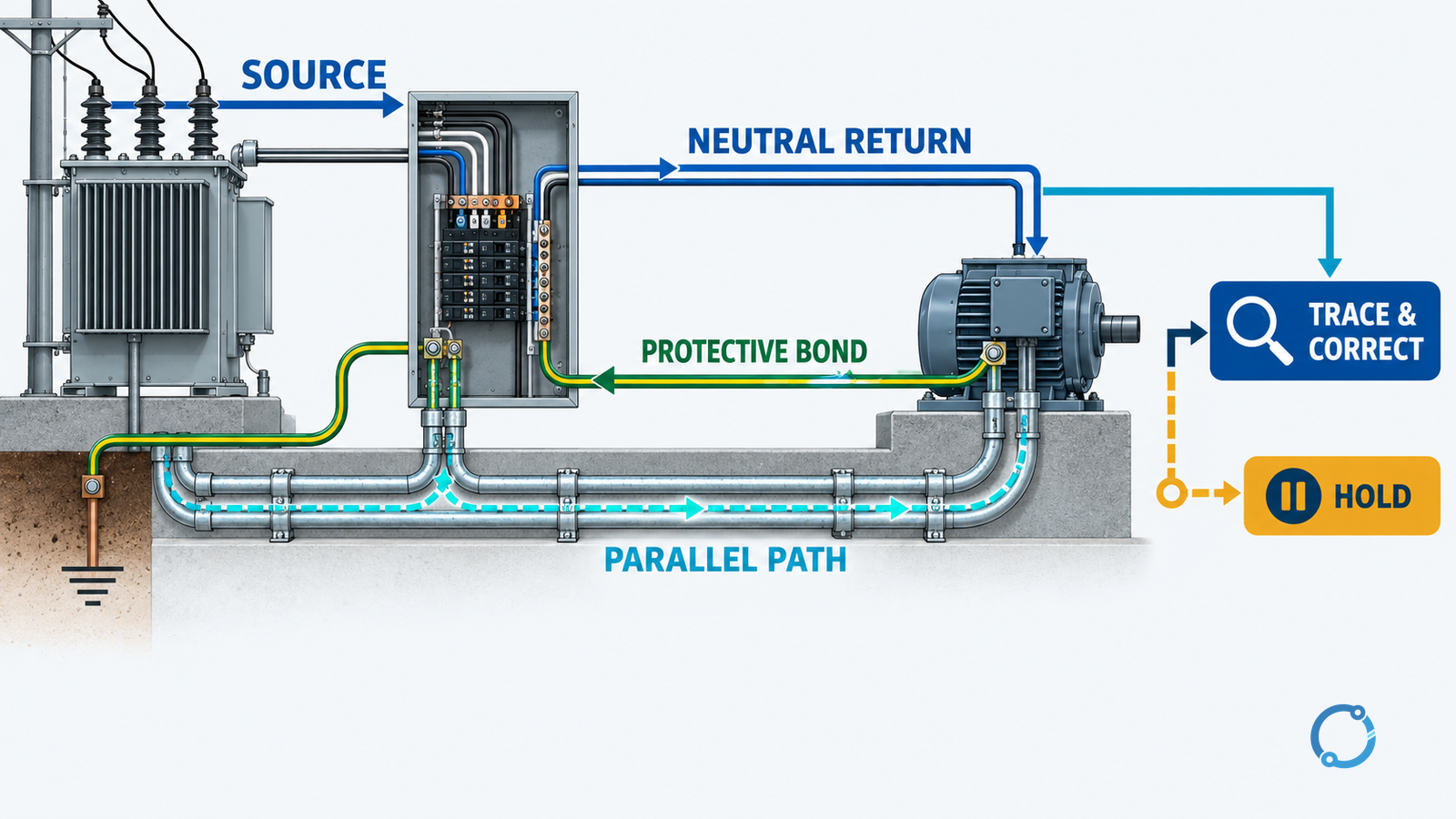
Mark which conductors are normally current-carrying and which are intended only for protective or functional current. Then look for a loop. Current needs a source and a closed circuit. If current crosses a bonding conductor in one direction, the return may use the neutral, another bonding path, building steel, a signal cable shield or an accidental contact.
The question is not simply “where is current highest?” It is “where does this particular current enter this path, and where does it leave?” Two clamp readings on opposite sides of a bonding system may agree yet still leave the source unresolved.
Gate 3: classify normal and unintended parallel paths
Several conditions can put current in metal or protective conductors without a conventional insulation failure.
Neutral current using bonded metal
If neutral current has more than one possible return path, a portion may divide through bonded metal. The proportion depends on impedances and cannot be judged from conductor size alone. The origin may be an accidental neutral-to-ground contact, a bonding arrangement that is correct in one location but duplicated elsewhere, a transfer switch configuration, or a separately derived system whose neutral-to-earth tie is not aligned with the system design.
The computer grounding noise guide handles an important lower-current version of this problem, but the same rule applies: removing protective earth is not the diagnostic solution.
Ground-fault current
An insulation failure or accidental contact between an energized conductor and bonded metal can create fault current. The amount may be large enough to operate a breaker quickly, or it may be limited by earth resistance, equipment impedance or the power source. A residual-current or ground-fault protective device may detect current that is too low to trip an overcurrent device.
A clamp reading alone cannot distinguish fault current from normal neutral current. Look for the fault’s source, the path to bonded metal, simultaneous voltage changes, protection events and insulation evidence. Do not repeatedly energize an unverified fault.
Circulating current
Parallel bonding between two points can create a loop that couples changing magnetic fields or joins points at different potentials. The current can be steady or intermittent and may rise when large loads cycle. This is common enough in complex buildings that “current on the ground” should never be assumed to mean “the ground is bad.”
Rectified, DC and power-electronic current
AC clamp meters do not necessarily measure DC accurately. Battery systems, rectifiers, variable-frequency drives, cathodic protection and electronic power supplies can produce current or ripple outside the range the instrument was selected for. A DC-capable clamp, a current transducer or an oscilloscope-based method may be needed. Instrument selection follows the expected waveform and the safety plan.
Capacitive or filter current
Surge-protective devices, filters and cable capacitance can pass small transient or continuous currents. The measured value may be normal for the equipment, but it is still not permission to disconnect protective bonding. Verify the equipment’s design, leakage specification and installation instructions.
Gate 4: choose a measurement that answers the question
A clamp meter is useful when it encircles exactly the intended conductor. It becomes misleading when the jaw includes several conductors whose fields cancel, when a cable sheath is bonded at both ends, or when an external magnetic field dominates the reading.
Use one of these evidence approaches only after the appropriate safe-work review:
- compare current in the suspected conductor with current in the neutral and phase conductors at the same point;
- repeat the reading at several locations to see where the current first appears and last disappears;
- correlate the reading with a controlled load state or known switching event;
- use a current transducer and recorder when the event is intermittent;
- use differential or residual-current measurement where the approved method and equipment allow it;
- verify voltage between equipment and reference points with a suitable meter and approved test procedure;
- inspect for accidental neutral-to-ground contact using the applicable isolation and continuity method;
- obtain an insulation or earth-loop test from a competent person when fault or earthing performance is suspected.
Do not rely on a single measurement taken at an arbitrary location. Two readings can be large while the current path remains unresolved. A small reading can still indicate a hazardous touch-voltage condition. The decision is based on topology, voltage, current, duration and protective-device response together.
Gate 5: separate normal return current from a fault
The following matrix is a starting point for the investigation, not a fault classifier:
| Evidence pattern | Possible explanation | Required next step |
|---|---|---|
| Current varies closely with a large single-phase load | A parallel neutral path or accidental neutral-to-earth connection | Trace the neutral and bonding connections with the circuit isolated under an approved procedure |
| Current rises during a transfer or generator operation | Changed source bonding or a transfer-switch neutral configuration | Compare the actual switching state with the approved single-point bonding design |
| Current appears with every load and is not proportional to one circuit | Circulating current between bonded structures or a common-path issue | Map all bonds and measure potential differences under controlled conditions |
| Current accompanied by a protective-device trip | Fault or overload-related event | Stop automatic reclosure and establish the protection and fault evidence |
| Current changes with capacitance, filters or electronic equipment | Functional leakage or high-frequency component | Use an instrument and manufacturer method that match the equipment’s declared characteristics |
| Current present but no source can be identified | Measurement error, externally induced current or an incomplete topology | Repeat with a better instrument and escalate to a system-level investigation |
If a fault is suspected and the protective device has operated, do not reclose merely to see whether the current remains. A repeated trip is an unresolved condition. The MCCB tripping diagnostic workflow applies the same event-first principle to low-voltage molded-case breakers. For earth-fault loop performance, use the controlled earth fault loop impedance testing method rather than treating a clamp reading as a substitute.
Gate 6: interpret voltage as well as current
Current indicates that a path is carrying current. Voltage difference indicates the possible consequence for people and equipment if that path or its connections change.
Relevant evidence may include:
- voltage between accessible equipment and the local reference;
- voltage across a bonding connection;
- voltage from neutral to earth;
- step or touch-voltage conditions evaluated by a qualified person;
- voltage distortion and high-frequency content;
- changes in voltage when a load or source is switched.
A low-resistance conductor can carry substantial current with little voltage drop, so a “normal-looking” voltage cannot exclude an unintended parallel path. Conversely, a high-impedance digital meter can show a misleading voltage on an isolated or capacitively coupled conductor. The measurement method must be suitable for the source impedance and the expected signal.
When touch voltage, arcing, heating, smoke, damaged insulation or an unknown source is present, the correct response is to establish an electrically safe work condition and escalate. Do not wait for a second measurement to justify stopping work.
Gate 7: inspect the installation for the point of contact
Once the system is safely isolated under the approved procedure, inspect the parts the measurements point toward:
- neutral and protective-conductor bars, including accidental contact between them;
- transfer switches and source-selection arrangements;
- separately derived systems and their bonding points;
- panelboard and enclosure bonding;
- cable shields, drain wires and metallic trays;
- equipment filters, surge devices and electronic power supplies;
- motor and drive connections;
- moisture, contamination, damaged insulation and loose terminations;
- recently added circuits, hidden splices and parallel feeders;
- neutral and ground bars that appear similar but serve different functions.
Do not treat cleaning, tightening, adding a bond or replacing a conductor as a repair until the electrical cause is understood. A parallel path may vanish when an accidental neutral contact is corrected, but a current-carrying protective conductor can also be a symptom of a missing or incorrectly located system bonding point.
Gate 8: repair, verify and record the new topology
The repair must match the fault family.
| Finding | Appropriate correction concept |
|---|---|
| Accidental neutral-to-earth contact | Remove the unintended connection and verify that neutral current returns by the intended path |
| Duplicated or misplaced system bonding | Restore the approved single-point bonding arrangement from the drawings and applicable code |
| Loose or damaged bonding connection | Replace or repair the connection and re-establish continuity before energization |
| Insulation or ground fault | Isolate the affected circuit, locate the failure and repair or replace the equipment |
| Incorrect transfer or generator bonding | Correct the switching and source-grounding design, not just the measured conductor |
| Circulating current through parallel bonding | Redesign the bonding or shielding arrangement with engineering approval |
| Instrument or measurement artifact | Use a correct instrument and method; do not alter the installation to satisfy a bad reading |
After the correction, verify the result with a planned test sequence. Repeat the current observation at the same locations and load states, inspect all disturbed connections, record voltage measurements and confirm that protective devices and alarms respond as designed. Compare the new topology with the approved drawings and update those drawings if the physical arrangement changed.
The main bonding jumper checks and equipment grounding conductor sizing pages are part of the handover. A quick clamp reading does not replace the design record.
Stop conditions
Stop the diagnostic work and escalate when any of the following applies:
- the protective conductor is damaged, hot, arcing or visibly carrying fault current;
- a person has received a shock or touch-voltage complaint is unresolved;
- a protective device has operated without a confirmed safe cause;
- the source or neutral bonding arrangement is unknown;
- multiple sources, transfer switches or separately derived systems are present;
- DC, high-frequency or complex waveforms are suspected but the instrument is not suitable;
- removing or interrupting a bond would affect equipment or personnel protection;
- the installation drawings disagree with what is installed;
- measurements cannot be repeated or reconciled by a qualified person.
An unexplained grounding current is not proof that a building needs an earth electrode driven deeper, a new grounding rod or a different grounding conductor. Such changes can create additional parallel paths and make the system less predictable. The investigation must identify the source, the return circuit and the purpose of every bond before changing the earthing design.
A practical investigation dossier
For each report, retain:
- the original complaint and exact location;
- the time, load and source configuration;
- single-line, grounding and bonding drawings;
- photographs of the conductor route and terminations;
- instrument details, settings and waveforms;
- current and voltage readings with repeatability notes;
- protection-event records;
- the fault-family decision and assumptions;
- isolation, repair and restoration records;
- post-repair readings and handover sign-off.
This record matters because objectionable current often changes with operating state. A second investigator should be able to reconstruct what was measured and why, without relying on a memory of “there was current on the ground.”
The practical conclusion
Diagnose grounding current by preserving protective bonding and mapping the complete electrical return path. Identify the source, the normal neutral return, the protective path and the unintended parallel path. Use instruments that match the waveform, validate every reading at more than one location, and stop when the evidence points to fault current, touch voltage, damaged bonding or an unknown source.
The right question is not “how much current is acceptable on this conductor?” It is “why is this conductor part of a closed circuit, and what will happen to the equipment and people if that path changes?”