
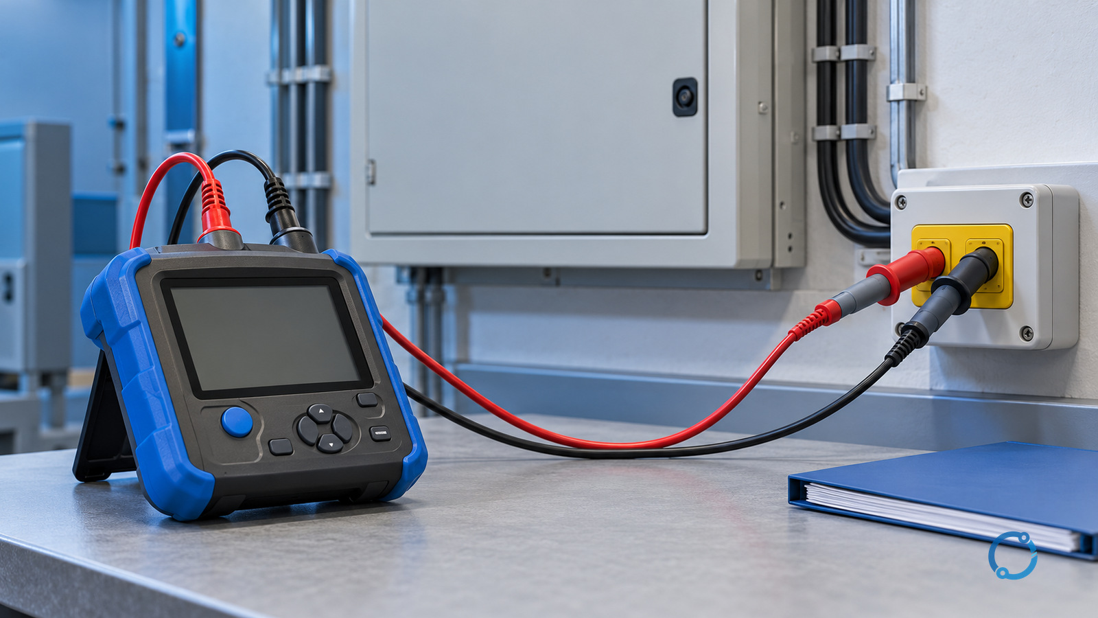
Earth fault loop impedance is the impedance of the intended current path from the source, through the line conductor, through the fault, back through the protective conductor or other earth-return path, and through the source earth connection. A loop-impedance test is useful only when it measures or establishes the relevant path at the relevant point, under a known supply condition, and with an instrument suitable for the job.
The result is then compared with the requirements for the actual installation and its protective devices. There is no single ohm value that can approve every socket, circuit and breaker. The UK framework is the most direct example: BS 7671:2018+A4:2026 is the current edition identified by the IET for UK electrical installations, and the acceptable values and disconnection times belong with the applicable protection criteria, not with a generic online chart.
This article is for qualified electrical personnel working on low-voltage installations up to the stated instrument scope. It explains how to choose among a dead-test calculation path, a direct live loop test and the verification evidence around them. It does not authorize live work, replace the adopted edition of BS 7671, or reproduce its licensed tables.
Put the loop test in the protection story
Protective devices must be able to clear an earth fault within the conditions required by the installation design. HSE guidance describes the earth-fault current as being governed mainly by the combined impedance of the fault loop, including the source, circuit conductors, earthing and protective conductors. The same guidance points to BS 7671 for acceptable earth-loop impedance and disconnection times for final installations up to 1,000 V.
This is why the test cannot be separated from the protective device. A reading may look low but belong to a circuit with an unsuitable device, a changed breaker curve, an altered transformer or a disturbed protective conductor. A reading may look high but have been taken on the wrong range, with a poor test connection, at the wrong point or under an unusual supply condition.
A sound loop-impedance plan starts with the following inputs:
| Input | Why it belongs in the record |
|---|---|
| Supply and earthing arrangement | It defines the expected fault-current path. |
| Protective-device type, rating and characteristic | It determines the current and time criterion for that circuit. |
| Circuit origin and final-circuit extent | They define which upstream and downstream conductors belong in the loop. |
| Conductor material and route | They affect the expected line and protective-conductor impedance. |
| Instrument and measurement route | Not every method produces the same quantity or confidence. |
| Prospective fault current basis | It is a derived or assessed system value, not just 230 V divided by a meter reading. |
| Adopted BS 7671 edition and project basis | They supply the actual pass/fail and verification requirements. |
The EWR 1989 duties are part of the legal background. Regulation 4 requires electrical systems to be constructed, maintained and worked on so as to prevent danger so far as reasonably practicable. A test plan with a good form but a missing authorized-person check is not a safe substitute for that duty.
Define Zs, Ze and R1+R2 before touching a tester
The terms refer to different quantities and different test questions.
| Quantity | Scope | Typical evidence route | Common mistake |
|---|---|---|---|
Ze |
External earth-fault-loop impedance at the origin, with the relevant installation conditions established | Measured at the origin by an approved method, or taken from a documented supply basis where permitted | Treating it as the Zs of every final circuit. |
R1+R2 |
Resistance of the line conductor and the associated circuit protective conductor for the specific circuit | Continuity measurement and route verification, or a controlled calculated value where the applicable method permits | Forgetting that joints, parallel paths and the actual circuit route change the value. |
Zs |
Earth-fault-loop impedance at the relevant point in the completed circuit | Direct measurement at the point of use, or a documented calculation from valid upstream and circuit values | Calling a calculation a measurement, or assuming the calculation is complete after adding two numbers. |
PSCC / PFC |
Prospective short-circuit or fault current derived from the source and circuit impedance under a stated method | Calculation from a measured or documented impedance basis, or a suitable instrument reading within its permitted method | Presenting the rounded number as a complete protection study. |
The familiar relationship for a simplified initial check is:
Zs ≈ Ze + R1 + R2
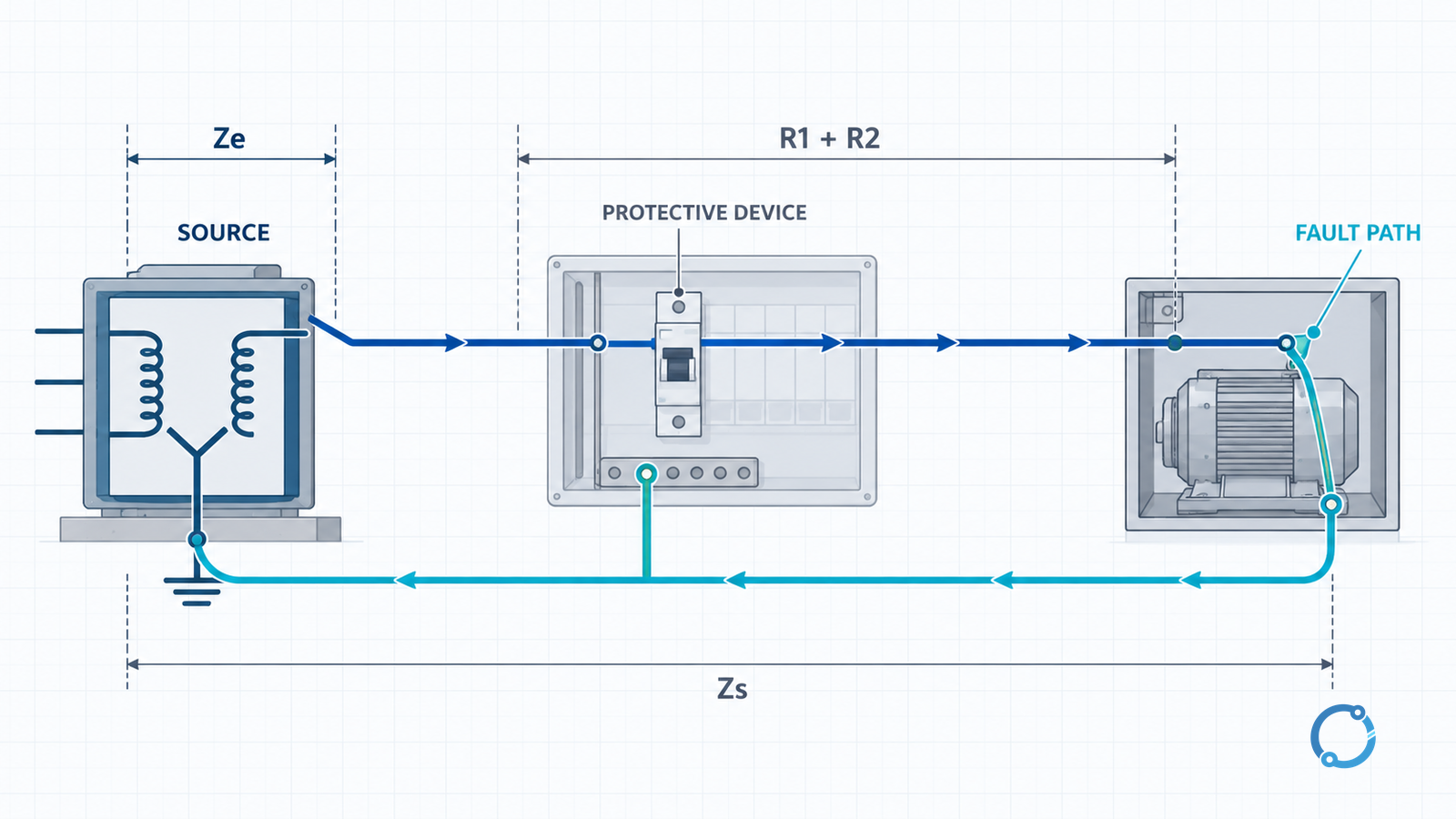
The symbol is only a starting relationship. It does not decide whether the circuit passes. The actual method, conductor temperature, supply voltage, protective device and local requirements determine how the calculation may be used. Check that all values use the same circuit path and the same measurement or calculation basis.
Where the earth-electrode article stops and this one begins
If the question is how a rod, grid or electrode network couples to the soil, the correct task is earth-electrode testing and soil resistivity. That page owns the electrode-specific test plan. This page owns the protective loop at the installation or final circuit. A TT installation may require an electrode resistance and an RCD-based protection assessment, but one electrode measurement is not a universal loop-impedance result.
The insulation resistance test is also a separate physical measurement. It applies a test voltage to de-energized insulation. It does not measure the impedance of an intended fault-current path or replace a continuity and loop check.
Establish competence and work control before the test
Loop impedance methods can involve energized conductors, temporary supply loading or temporary disconnection of a protective conductor. The work must be assigned to a competent person under the applicable safe system of work. The following gates come before a reading:
- Define the circuit boundary. Identify the source, protective device, circuit origin, test point and intended fault path.
- Check the instrument duty. Verify that the tester is suitable for the installation’s voltage, frequency, measurement category and the exact loop method. IEC 61557-3:2019 covers loop-impedance measuring equipment within its low-voltage scope; it is not a brand certificate or a pass/fail value for an installation.
- Confirm the test leads and guards. Use the approved leads, probes and tip guards, check continuity and insulation where required, and confirm the instrument’s self-test or lead-compensation routine.
- Apply the site’s isolation or live-work control. Do not create a temporary hazardous condition merely to obtain a direct reading. If a protective conductor must be temporarily disconnected, follow the authorized procedure, not an improvised clip.
- Control the supply state. Record the supply voltage and relevant source arrangement. A generator, UPS, isolating transformer or parallel source can change the measured condition.
- Protect the working area. Apply the site’s PPE, barriers and communication requirements. Test equipment must not be left where another person can contact it or restore the supply.
- Have a stop rule. Stop if the instrument gives unstable results, the leads are suspect, the circuit behaves differently from the test setup or the test would require exceeding the authorized work boundary.
GS 38 provides guidance on test probes and leads for electrical test equipment used by electricians. It is not permission to work live; it supports the selection of suitable safe test accessories within an authorized procedure.
Choose the loop-test route that answers the question
There are useful method options, but they are not interchangeable.
| Method | What it can answer | Main condition or limitation |
|---|---|---|
| Direct loop-impedance measurement | The impedance of the selected line-to-protective-conductor, line-to-neutral or line-to-line path under the test condition | The instrument must be suitable, the test point correct and the live/test state properly controlled. |
Ze measurement at the origin plus R1+R2 measurement for the circuit |
A calculated Zs basis that can be checked and audited circuit by circuit |
The values must represent the same path and the applicable standard must permit the calculation method. |
| Continuity testing of protective conductors plus other design evidence | A check of the protective path and a documented basis for further assessment | Continuity alone does not establish the complete earth-fault-loop impedance or disconnection performance. |
| Calculation from valid source and circuit data | A prospective design or verification basis where the input data and method are valid | A theoretical value should not be presented as a field measurement or proof that the installed route matches the drawing. |
| RCD or protective-device test | Verification of the device function within its specified test procedure | It is not a substitute for confirming the complete loop and protection design. |
IEC 61557-3:2019 describes instrument requirements for direct loop impedance using the voltage drop when the circuit is loaded and includes line-to-protective-conductor, line-to-neutral and line-to-line measurement paths. The standard edition’s measurement-category and operating-instruction requirements are part of the instrument check. They do not tell you whether a particular socket is safe or a particular breaker will trip in time.
Direct measurement is not automatically the best evidence
A direct Zs reading is persuasive because it includes the installed path. It can still be invalid if:
- the test point is not at the relevant part of the circuit;
- the neutral and protective paths are not the ones the device uses;
- a parallel path or temporary bond alters the result;
- the instrument is on the wrong function, range or voltage basis;
- electronic loads, harmonics or supply conditions disturb the test;
- the reading is taken during a switching state that will not represent the verified installation.
Record the route, state and instrument. A number without those facts is not a reproducible result.
Calculation is a legitimate check only when its basis is controlled
A calculated Zs can let a verifier check many final circuits without treating every test as an identical live measurement. It is strongest when the upstream basis, protective-conductor continuity and circuit route are all documented. It becomes weak when the calculation recycles a nominal source value, ignores conductor temperature or uses a cable route that cannot be verified.
Do not add Ze and an R1+R2 value with different temperatures, units or path assumptions and then call the result a measurement. If the adopted standard permits a calculated value, retain the inputs and the method reference.
Run the instrument and connection checks before accepting a reading
The detailed test sequence belongs to the instrument’s approved instructions and the site procedure. The evidence checks are more stable:
- verify battery, self-test and any manufacturer-required calibration status;
- inspect leads and probes for damage, continuity and correct guard fit;
- use the correct lead compensation or nulling method if the tester requires it;
- confirm the selected voltage and fault-loop function;
- verify the test point and supply polarity or phase sequence as applicable;
- take the reading only within the authorized live or de-energized state;
- repeat or cross-check an unexpected value before using it;
- record the displayed value, unit, instrument mode and any range or resolution limitation;
- return the installation to its verified state and prove it.
An instrument that reports a single low number is not necessarily giving a high-quality result. Look for a stable display, sensible repeatability and a result whose order of magnitude fits the known source and circuit. A reading that changes when the lead is moved may be a connection problem rather than a changing installation.
Use a candidate precheck, not a universal threshold
For a rough engineering sanity check, one may estimate the prospective current from the measured voltage and loop impedance:
I ≈ U / Z
For example, with an illustrative 230 V nominal basis and a measured earth-fault loop impedance of 0.80 Ω, the arithmetic gives about 288 A. With 1.60 Ω, it gives about 144 A.
These are arithmetic examples, not acceptance values. The actual protective device’s current-time behavior, the adopted edition of BS 7671, the circuit type and the measured voltage basis must all be applied. A 288 A result does not automatically mean a particular breaker will disconnect in the required time; a 144 A result does not automatically mean the circuit fails.
The formula also shows why the “prospective fault current” should not always be computed from a nominal 230 V label. Use the actual supply and method basis for the decision, and keep the calculation traceable.
Interpret the result against the right criterion
The interpretation has two layers:
- Path and measurement validity: did the test measure the intended loop at the intended point with a suitable instrument and traceable state?
- Protection and installation compliance: does the resulting value satisfy the requirements for this circuit’s protective device, disconnection time and adopted edition?
A result can pass the first layer and still need action because the second layer has changed. Examples include a replacement breaker with a different curve, a circuit extended beyond its original route, a changed supply arrangement, a repaired protective conductor or a new final circuit with a different disconnection requirement.
The reverse is also possible: a measured value may be surprising while the calculation and protection basis still need review. Do not replace a breaker or change a protective conductor simply to make the ohm reading look better. First establish the criterion and the source of the discrepancy.
What to record with every Zs result
- Circuit and protective-device identity.
- Test point and the line-to-protective-conductor path tested.
- Instrument, function, range and lead arrangement.
- Measured voltage and stable loop-impedance value.
- Supply source state and any parallel or temporary paths.
- Calculation inputs if Zs was derived.
- Protective-device type, rating and characteristic.
- Applicable BS 7671 edition and protection criterion.
- Pass, fail, indeterminate or investigation-required outcome.
- Corrective action, retest and restoration record.
This is the minimum record that another competent person can audit. A photograph of a meter display without the circuit and criterion is not enough.
Recognise the common errors that create a false answer
| Error | Effect | Control |
|---|---|---|
| Using the wrong instrument function | Measures a different loop or includes unintended loading | Match the instrument mode to the standard and test point. |
| Testing at the wrong end of the circuit | Omits part of the line or protective path | Mark the source and test point on the circuit plan. |
| A poor probe connection | High or unstable reading that is blamed on the installation | Inspect, null and repeat with the approved lead procedure. |
| A parallel path is present | A lower reading that does not represent the intended protective path | Identify temporary and permanent parallel paths. |
| A calculated value is recorded as measured | Overstates the evidence and hides route uncertainty | Keep the evidence route explicit in the record. |
| The wrong BS 7671 edition is used | Compares against a superseded criterion | Check the IET edition page and the project’s adopted basis. |
| A source change is ignored | Tests one supply condition and applies it to another | Record generator, UPS, parallel or transformer states. |
| A device is changed without a coordination check | The loop now serves a different protective characteristic | Review the complete protection change, not only the ohm value. |
The neutral earthing system selection page explains why the source earthing and return path are design choices with consequences. It does not let a loop test substitute for that selection or vice versa. For the upstream protective device’s relationship to conductor protection, use the cable and circuit-breaker feeder verification guide.
Stop, repeat or escalate
Stop the test and escalate when:
- the required work would exceed the tester’s authorization or the site’s safe work control;
- the instrument or leads are damaged, unstable or unsuitable;
- the reading is not repeatable or does not match the physical circuit;
- the protective conductor or bonding arrangement is uncertain;
- a supply source or parallel path is not under control;
- the result falls outside the applicable criterion and the corrective action is not yet verified;
- a protective device or circuit has been altered since the design basis;
- the adopted BS 7671 edition or the project’s basis cannot be established.
The result is not complete until the installation is restored, the evidence is recorded and the person responsible for the protective measure has accepted the outcome. A tester who has only a meter reading has not necessarily completed the verification.
A practical completion rule
An earth-fault-loop impedance test is complete when all five statements are true:
- The relevant fault path and test point are identified.
- The instrument and method match the circuit and the authorized work state.
- The reading or calculation is stable, traceable and recorded with its basis.
- The result is compared with the protection and installation criteria in the adopted edition.
- The installation is restored and any stop, repair or escalation condition is closed.
That rule keeps the method, the measurement and the compliance decision separate. It also makes the distinction between a useful field reading and an unsupported “good earth” claim.
Sources
- IEC 61557-3:2019: Equipment for measuring loop impedance, published 2019-07-26, edition 3.0.
- IET: BS 7671 current edition and transition guidance, page checked 2026-10-25.
- The Electricity at Work Regulations 1989, regulation 4, original made version checked 2026-10-25.
- HSE HSR25: The Electricity at Work Regulations 1989 Guidance, earth-fault-loop guidance in paragraphs 132-135, checked 2026-10-25.