

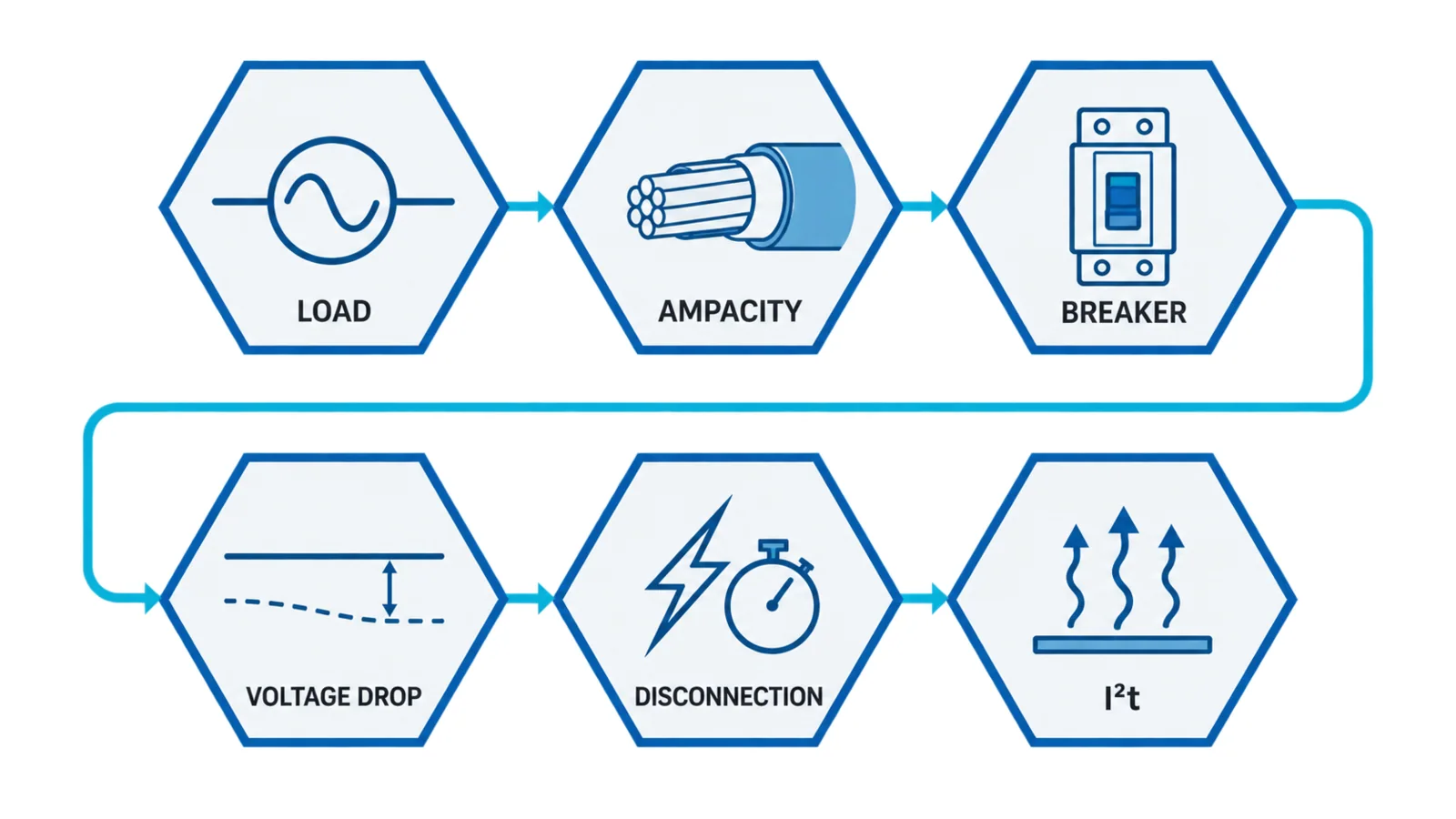
For an LV feeder protected by a circuit breaker, choose a cable whose corrected current-carrying capacity covers the load and the breaker’s effective overload setting. Then verify voltage drop, automatic disconnection for the minimum fault current, conductor thermal withstand for the maximum fault energy, neutral/protective-conductor requirements and the breaker’s interrupting rating.
The frame size printed on a breaker is not enough. Adjustable long-time, instantaneous and ground-fault settings—and the installation conditions used to derive cable ampacity—control the coordination.
Scope and governing documents
This workflow applies to preliminary sizing of low-voltage feeders under the IEC 60364 framework using a circuit breaker within the scope of IEC 60947-2. It does not replace the locally adopted wiring rules, a protection study, manufacturer time-current data, or qualified design review.
IEC 60364-5-52:2009+A1:2024 covers selection and erection of wiring systems, including current-carrying capacity, harmonics, voltage drop, connections and maintainability. IEC 60364-4-43:2023 covers protection of conductors against harmful overcurrent and coordination of protective measures.
IEC 60947-2:2024 applies to circuit breakers for circuits up to 1,000 V AC or 1,500 V DC within its scope. Product settings, tolerances and let-through data remain device-specific.
Inputs required before calculation
System
- nominal voltage, phases and frequency;
- earthing arrangement;
- maximum and minimum source fault levels;
- transformer/generator impedance and operating configurations;
- required disconnection times under the adopted rules;
- upstream/downstream protective devices and selectivity objective.
Load
- design current or power, power factor and efficiency;
- continuous, cyclic, motor-starting or transformer-inrush duty;
- harmonic spectrum and expected neutral current;
- future load allowance;
- permissible voltage drop at steady state and starting.
Cable route
- conductor material and insulation;
- multicore or single-core arrangement;
- installation/reference method;
- ambient air or soil temperature;
- grouping and spacing;
- thermal insulation, ducts, trays and buried depth;
- soil thermal resistivity and drying assumptions;
- route length and parallel circuits;
- termination temperatures and equipment limits.
Circuit breaker
- standard and utilization category;
- frame and sensor/rating-plug current;
- long-time pickup and delay;
- short-time pickup/delay and I²t mode;
- instantaneous setting;
- ground-fault function;
- rated operational voltage;
- ultimate/service short-circuit breaking capacity as applicable;
- let-through energy/current data;
- tolerances and ambient effects.
Gate 1: calculate design current
For a balanced three-phase load:
Ib = P / (√3 × V × PF × η)
where:
- Ib is design current in A;
- P is output power in W when efficiency is included;
- V is line-to-line voltage;
- PF is power factor;
- η is efficiency.
Use measured or specified current when it better represents the duty. For multiple loads, apply diversity only when the operating logic and applicable rules support it. Keep starting current separate from continuous design current.
Example load
Assume:
- three-phase load output: 250 kW;
- voltage: 400 V;
- power factor: 0.90;
- efficiency: 0.95.
Ib = 250,000 / (√3 × 400 × 0.90 × 0.95) ≈ 422 A
This is the continuous design-current estimate. Motor starting or cyclic peaks require separate voltage-drop and breaker-operating checks.
Gate 2: derive corrected cable capacity
Obtain the tabulated current-carrying capacity It from the adopted wiring standard for the exact conductor and installation method. Apply the correction factors required by that method:
Iz = It × Ca × Cg × Ci × Cs × …
where, depending on the route:
- Iz is corrected current-carrying capacity;
- Ca corrects ambient temperature;
- Cg corrects grouping;
- Ci addresses thermal insulation;
- Cs may address soil or another defined installation condition.
Use only factors intended to be combined. Some tables already incorporate conditions represented elsewhere; careless multiplication can double-count a derating.
For parallel conductors, verify:
- same material and cross-section;
- equal or controlled route length and impedance;
- symmetrical physical arrangement;
- appropriate grouping factors;
- common termination quality;
- current sharing under harmonics and magnetic effects.
Do not divide total current by the number of parallel cables without verifying sharing and installation derating.
Gate 3: coordinate load, breaker and cable
A widely used IEC coordination relationship for overload protection is:
Ib ≤ In ≤ Iz
where In represents the protective-device rated current or effective setting as defined by the applicable rule. For an adjustable breaker, use the setting that actually controls overload protection, not automatically the frame size.
The second condition commonly expressed in IEC-based design is:
I2 ≤ 1.45Iz
where I2 is the current ensuring effective operation of the protective device in the conventional time. The exact interpretation and device data must follow the adopted standard and breaker documentation.
For the 422 A example, suppose a candidate cable arrangement has:
- tabulated capacity It = 535 A;
- ambient factor Ca = 0.91;
- grouping factor Cg = 0.90.
Then:
Iz = 535 × 0.91 × 0.90 ≈ 438 A
If the breaker’s effective long-time pickup is set to 430 A, the first relationship is:
422 A ≤ 430 A ≤ 438 A
It passes narrowly. The design remains incomplete until the trip tolerance, cable terminal limits, harmonics, voltage drop and fault checks pass. A 500 A frame does not invalidate the design if an accepted 430 A protective setting controls the cable; conversely, a 500 A frame left effectively at 500 A would not satisfy this example.
Gate 4: check voltage drop
For a balanced three-phase circuit:
ΔV = √3 × I × L × (R cosφ + X sinφ)
where:
- L is one-way route length;
- R and X are conductor resistance and reactance per unit length at the relevant condition;
- φ is the load phase angle.
Voltage-drop limits depend on local rules and the load. Calculate:
- normal running drop;
- starting or inrush drop;
- remote-end voltage under minimum source voltage;
- drop in neutral where harmonic or unbalanced current is material.
Use conductor resistance at expected operating temperature. A cable can pass ampacity yet fail voltage drop on a long route. Upsizing may be required even when the breaker coordination already passes.
Example voltage-drop structure
For the selected cable, take project-verified hot R and installation-specific X values. For a 120 m route and 422 A load:
ΔV = √3 × 422 × 0.120 × (R cosφ + X sinφ)
Do not substitute generic impedance numbers here. Cable construction, formation and temperature determine them. The calculation sheet should show the source of R and X, the resulting volts and percentage, and the project acceptance limit.
Gate 5: verify fault detection and disconnection
Calculate the minimum fault current at the remote end under the least favorable credible source voltage and maximum loop impedance. Compare it with the breaker’s time-current characteristic including tolerance.
Questions to answer:
- Will the breaker operate within the required disconnection time?
- Does the selected instantaneous setting detect the minimum bolted fault?
- If not, does the short-time or ground-fault function clear it within the conductor limit?
- Could motor starting or transformer inrush cross the pickup?
- Does a high instantaneous setting create an unprotected region?
- Is the earthing arrangement correctly represented?
Maximum fault current checks interrupting duty; minimum fault current checks sensitivity and disconnection. Both are required.
Ground-fault protection can be decisive where phase-to-earth current is below instantaneous pickup. Its settings and sensing arrangement must coordinate with the earthing system, upstream devices and desired selectivity.
Gate 6: verify short-circuit thermal withstand
For a simplified adiabatic check:
S ≥ √(I²t) / k
or equivalently:
I²t ≤ k²S²
where:
- S is conductor cross-section;
- I²t is fault energy over the clearing interval;
- k depends on conductor and insulation materials plus initial/final temperatures.
Use the k value and applicability rules from the adopted standard. Check phase, neutral and protective conductors separately.
The breaker input can be:
- time-current clearing time with prospective RMS current, when appropriate;
- manufacturer let-through I²t for current-limiting operation;
- a detailed protection-study result.
Do not combine prospective current with an unrelated clearing time. At high fault levels, a current-limiting breaker may substantially reduce let-through energy; at lower levels, its time-delay region can govern.
Also verify:
- the breaker’s rated breaking capacity at the system voltage;
- peak let-through against equipment withstand;
- cable screen/sheath and protective-conductor duty;
- termination and busbar short-circuit ratings;
- backup/cascading claims only for tested or documented combinations.
Keep overload and short-circuit checks separate
The same breaker has different operating regions:
| Region | Main purpose | Cable check |
|---|---|---|
| Long-time | overload protection | Ib, effective pickup, Iz, thermal memory |
| Short-time | selective short-circuit protection | minimum fault sensitivity, delay and I²t |
| Instantaneous | rapid high-fault clearing | pickup tolerance, inrush immunity, let-through |
| Ground-fault | earth-fault protection | earthing system, minimum earth-fault current, selectivity |
A cable may be protected against overload but not against a remote low-current earth fault. It may pass the adiabatic high-fault check but operate above its continuous ampacity because the long-time setting is too high.
Neutral and protective conductors
Do not reduce neutral size by habit. Evaluate:
- load imbalance;
- third and triplen harmonics;
- single-phase nonlinear loads;
- phase conductor size and overcurrent protection;
- whether the neutral is switched or protected;
- local minimum-size rules.
For the protective conductor, evaluate fault current, disconnection time, material, route, bonding and the adopted sizing method. A separate protective conductor and a cable armour/screen do not automatically have equivalent fault performance.
Breaker-setting record
The cable calculation should not end with “630 A MCCB.” Record:
| Parameter | Required record |
|---|---|
| Frame/sensor | frame size, sensor or rating plug |
| Long-time | pickup, delay, tolerance, thermal memory |
| Short-time | pickup, delay, I²t on/off |
| Instantaneous | pickup and tolerance |
| Ground-fault | pickup, delay, sensing method |
| Breaking duty | Icu/Ics or applicable ratings at system voltage |
| Coordination | upstream/downstream curves and study reference |
| Locking | seal/password/label controlling settings |
| Commissioning | secondary/primary injection or approved functional test |
Settings that protect the cable must be controlled after commissioning. If an operator can raise them without review, the design basis is not preserved.
Complete worked-check summary
For the illustrative 250 kW load:
- Load current: approximately 422 A.
- Corrected cable capacity: approximately 438 A from the assumed table value and factors.
- Long-time setting: 430 A gives 422 ≤ 430 ≤ 438.
- Voltage drop: pending project cable R/X, route and acceptance limit.
- Minimum fault/disconnection: pending loop impedance and breaker curve.
- Short-circuit thermal withstand: pending maximum fault, clearing/let-through I²t and the applicable k.
The example deliberately remains “not released” because three gates need project data. A good calculation exposes missing evidence rather than manufacturing a pass.
Final design checklist
- Confirm locally adopted IEC-based rules and editions.
- Calculate design current and separate starting/inrush duty.
- Select the exact cable construction and installation method.
- Apply compatible correction factors to obtain Iz.
- Coordinate Ib, effective breaker setting and Iz.
- Check normal and transient voltage drop.
- Calculate minimum remote fault current and disconnection time.
- Calculate maximum fault duty and conductor I²t withstand.
- Verify breaker breaking capacity and equipment SCCR/withstand.
- Check neutral, protective conductor, parallel sharing and harmonics.
- Document and lock protective settings.
- Review selectivity, arc-flash objectives and commissioning tests.
Bottom line
Cable sizing for a circuit-breaker-protected feeder is a sequence of independent gates. Ampacity establishes the continuous thermal boundary; breaker settings provide overload and fault protection; voltage drop protects load performance; and minimum/maximum fault studies verify disconnection and thermal withstand. Release the design only when the complete chain is documented under the locally adopted rules.