
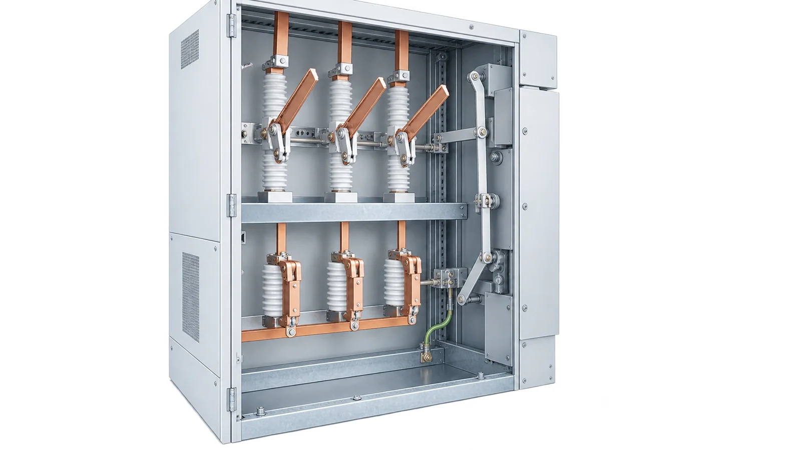
Select a medium-voltage disconnector to establish the specified isolating condition after another device has interrupted the load. Select an earthing switch to connect an isolated circuit to earth and, when the system risk requires it, specify a short-circuit making class. Neither name implies general load- or fault-current interruption.
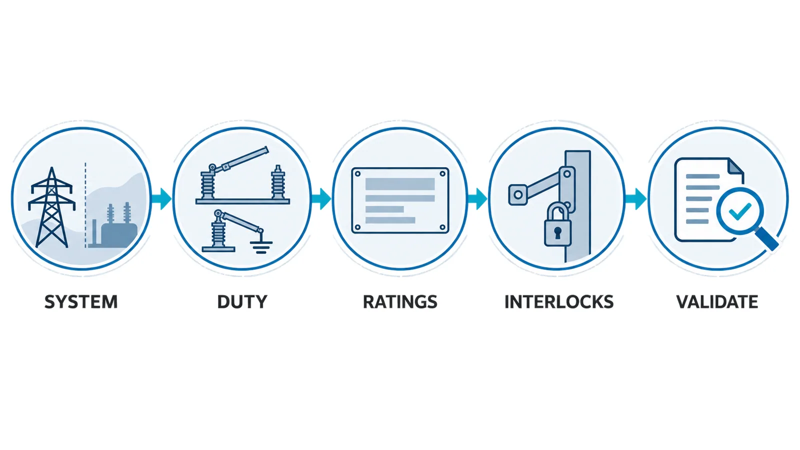
For an IEC specification, define the system voltage and insulation level, continuous and short-time current, any bus-transfer or charging-current duty, earthing-switch making duty, mechanical endurance, service conditions, position indication and interlocking. Then verify those functions in the complete switchgear assembly.
Scope and canonical boundary
IEC 62271-102:2022 EXV incorporates IEC 62271-102:2018+A1:2022 and applies to AC disconnectors and earthing switches for indoor and outdoor installations above 1,000 V at frequencies up to 60 Hz. It also covers equipment that combines disconnecting or earthing functions with other functions.
This article owns the detailed selection task. For a broader distinction among circuit breakers, load switches, contactors, fuses and isolating devices, start with OHELE’s switching devices in medium-voltage switchgear.
The functional difference
| Question | Disconnector | Earthing switch |
|---|---|---|
| Primary function | establish an isolating distance or equivalent assured isolation | intentionally connect an isolated conductor to earth |
| Normal load interruption | not a general load-breaking function | not applicable |
| Fault interruption | no general fault-breaking duty | not a fault interrupter |
| Closed-position current | may carry rated normal and short-time current | carries fault current when closed under specified conditions |
| Making duty | only named duties declared for the design | may require classified short-circuit making capability |
| Operating sequence | normally opens after the interrupting device | normally closes after isolation and verification steps |
| Key evidence | isolation, position indication, withstand and limited switching ratings | making class, withstand, position indication and interlocks |
Some three-position devices combine connected, disconnected and earthed positions. The combination does not erase the functional boundaries. The rated and tested assembly must define which transitions are possible and under what conditions.
Step 1: define the system boundary
Record:
- highest voltage for equipment;
- frequency and system grounding;
- insulation coordination and required withstand voltages;
- indoor/outdoor location;
- ambient temperature, altitude, pollution, humidity and ice where applicable;
- maximum RMS short-circuit current and duration;
- peak short-circuit current;
- bus arrangement, transfer conditions and induced-voltage sources;
- manual, motor or stored-energy operation;
- remote-control and auxiliary-supply requirements.
Do not use nominal system voltage as the only insulation input. The complete switchgear insulation level and service environment control the requirement.
Step 2: specify disconnector ratings
Rated normal current
The closed disconnector must carry the circuit’s required continuous current without exceeding applicable temperature limits. Coordinate the rating with busbars, contacts, terminals and the enclosure. Emergency loading needs an explicit duty and thermal basis.
Rated short-time and peak withstand current
The disconnector may be closed during a downstream fault even though it does not interrupt that fault. Specify:
- RMS short-time withstand current;
- rated duration;
- peak withstand current;
- system X/R or asymmetry data where required by the study.
The values must cover the prospective duty and the clearing time of the protective system. Mechanical supports and conductors in the assembly share this duty.
Insulating and isolating performance
Specify the applicable insulation level and isolating function. The open position must provide the standard-defined isolation performance and reliable position indication. A mimic symbol or motor command is not, by itself, proof of contact position.
Limited switching duties
Disconnectors can have named capabilities for duties such as:
- bus-transfer current;
- bus-charging current;
- small capacitive current;
- induced current in specified earthing applications.
The 2022 IEC publication page highlights ratings for bus-transfer current/voltage and classification of bus-charging switching capability. Specify these only when the one-line and operating study create the duty. Never translate a limited-current rating into permission for general load switching.
Mechanical endurance
Estimate expected operations over the service life:
Nlife = operations per year × design years + test/maintenance allowance
Match that number to the declared mechanical endurance class and maintenance plan. Frequent process switching normally belongs to another device class.
Step 3: specify earthing-switch duty
Short-circuit making capability
An earthing switch may be required to close onto a circuit that is accidentally energized. Where that risk is part of the design basis, specify the appropriate making capability/class and the prospective peak and RMS duties.
Short-circuit making capability means the device can survive the specified closing event and carry the resulting current for the rated interval. It does not mean:
- the action is a normal operating method;
- the switch interrupts the fault;
- voltage absence checks can be omitted;
- personnel may approach before the approved safety process is complete.
Short-time and peak withstand
After closing, the earthing path must withstand fault current until protection clears the source. Include the earthing switch, connecting conductors, joints and enclosure earth circuit in the verification.
Induced-current switching
Long lines, parallel circuits and nearby energized conductors can create inductive or capacitive currents. Where an earthing switch must make or break such current, identify the system calculation and specify the corresponding rated duty. Do not infer it from short-circuit making class.
Mechanical endurance and operating force
Specify expected operations, mechanism type, manual operating interface and motor/control supply where fitted. Environmental extremes can affect mechanism performance; the IEC 62271-102 publication notes mandatory high/low-temperature testing when declared service limits exceed +40°C or fall below −5°C.
Step 4: engineer the interlocking matrix
The selection is incomplete without state logic. A typical functional matrix might require:
| Existing state | Permitted action | Required prevention |
|---|---|---|
| breaker/load switch closed | none toward isolation | prevent disconnector opening under load |
| interrupting device open | open disconnector | prevent unintended reclose during transition |
| disconnector open / isolated | close earthing switch after approved checks | prevent closing if connected state remains |
| earthing switch closed | access under the approved safety procedure | prevent source switching or disconnector close |
| access door open | only actions permitted by the assembly design | prevent hazardous energization |
This table is conceptual. The actual matrix must come from the one-line, equipment design, operating philosophy and risk assessment. It must account for electrical, mechanical and key interlocks, auxiliary contacts, remote commands and loss of control power.
IEC 62271-102:2022 explicitly includes revised requirements for position indication and mechanical interlocking. Verify the complete mechanism and indication chain, not just the primary contact.
Step 5: define position indication
Record how each state is proven:
- direct mechanical indication;
- reliable position-indicating device;
- auxiliary contacts;
- mimic diagram;
- remote supervisory signal;
- viewing window where provided.
Separate local mechanical state from remote indication. A supervisory contact can fail or become misadjusted. The operating procedure should state which indication is authoritative for each action and how disagreement is handled.
Step 6: check the complete assembly
The device can be compliant yet misapplied in an assembly. Verify:
- conductor and earth-path withstand;
- clearances and barriers;
- accessibility and service-continuity arrangement;
- interlocks across adjacent compartments;
- internal-arc requirements where specified;
- cable earthing and test access;
- transfer-bus operating states;
- remote/automatic control inhibit;
- operation under loss of auxiliary power;
- nameplates, mimic and instructions;
- type-test or design-verification evidence for the actual arrangement.
For metal-enclosed switchgear, coordinate with the applicable IEC 62271 assembly standard. Device ratings are necessary but do not prove complete-switchgear performance.
Worked selection example
Assume a 24 kV indoor feeder panel with:
- 1,250 A continuous duty;
- 25 kA RMS short-time current for 3 s;
- project peak current from the short-circuit study;
- motor-operated disconnector;
- fixed earthing switch;
- no planned load-current switching by the disconnector;
- remote operation prohibited while the earthing switch is closed.
The specification should require:
- a disconnector with matching voltage/insulation, 1,250 A normal current and at least the stated short-time/peak withstand;
- no general load-breaking claim; any required bus-transfer duty stated separately;
- an earthing switch whose making class and withstand cover the project fault duty;
- mechanical endurance covering forecast operations;
- positive local position indication and defined auxiliary signalling;
- interlocks preventing disconnector operation under load and energization while earthed;
- assembly evidence for conductors, enclosure, earth path and interlock sequence.
The example is not a universal rating set. The system study supplies the actual insulation and fault values.
Safe operating boundary
Selection does not authorize switching or maintenance. Only trained and authorized personnel should operate MV equipment under an approved site procedure.
For U.S. electric-power work within its scope, OSHA’s de-energizing guidance explains that equipment is treated as energized unless the applicable de-energizing requirements are met and emphasizes protective grounding. Local rules may require additional visible isolation, voltage testing, grounding and clearance controls.
An earthing-switch indication is not a substitute for the complete safety process. Never defeat an interlock or force a mechanism whose state is uncertain.
Procurement checklist
| Group | Required data |
|---|---|
| System | voltage, frequency, grounding, insulation level |
| Current | normal current, short-time RMS/duration, peak current |
| Disconnector duty | isolation type, limited switching duties, endurance |
| Earthing duty | making class, withstand, induced-current duty |
| Service | indoor/outdoor, temperature, altitude, pollution, ice |
| Mechanism | manual/motor, supply, operating time, fail state |
| Indication | local state, auxiliary contacts, remote points |
| Interlocks | complete state/action matrix and override policy |
| Assembly | interfaces, earth path, access, internal-arc needs |
| Evidence | standard edition, ratings, type tests, routine tests, drawings |
Bottom line
Specify MV disconnectors and earthing switches by their actual duties. A disconnector establishes isolation and withstands current while closed; an earthing switch establishes an earth path and may need a defined short-circuit making class. Limited switching ratings, position indication, endurance and interlocks must come from the system and operating philosophy. Final acceptance belongs to the complete tested switchgear arrangement.