
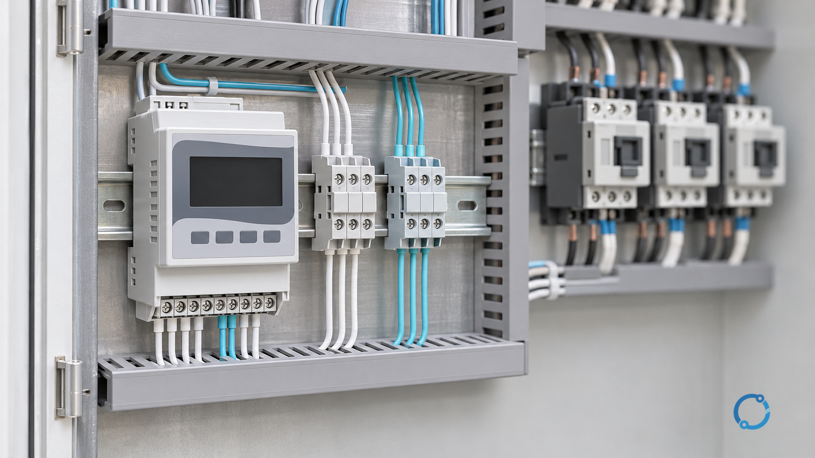
A power-factor relay is a measurement and control device, not a complete capacitor-bank design. Its wiring must answer four questions: what voltage and current does it measure, how does it know the phase relationship, what does it command, and how is the installation isolated and verified?
The same functional blocks appear on low-voltage (LV) and medium-voltage (MV) systems, but the physical interfaces are not interchangeable. An LV panel may use direct control wiring and a low-voltage auxiliary supply. An MV installation may involve instrument transformers, separated compartments, interlocking, remote control, and a more extensive commissioning procedure. The relay’s logic may be similar; the electrical and safety boundary is not.
This guide provides a practical interface schedule for a PF relay. It deliberately stops before capacitor-step sizing and protection coordination. Those are separate design tasks. The goal here is to make every relay connection visible, testable, and traceable from the approved drawing to the commissioning record.
Start with the measurement chain
A PF relay calculates active and reactive power from voltage and current measurements. The voltage input establishes the phase voltage or line voltage reference. The current input establishes the magnitude and phase of the current. The relay combines those measurements to derive quantities such as active power, reactive power, displacement power factor, or true power factor, depending on its design and configuration.
That means the relay is only as meaningful as its measurement chain:
- the voltage transformer (VT) or direct voltage connection must represent the intended system voltage;
- the current transformer (CT) or current sensor must be on the correct conductor;
- the CT ratio and polarity must match the relay’s configuration;
- the phase sequence and phase assignment must be consistent with the voltage reference;
- the secondary burdens and wiring must be within the approved design; and
- the measurement must be taken at the point that the control scheme intends to correct.
A relay can display a plausible number while being connected to the wrong phase or using an inverted current reference. The display alone is not proof of correct polarity. The commissioning process must compare the relay’s voltage, current, power, and phase-angle readings with an independent reference or a known load condition.
The OHELE guide to CT and VT selection explains the broader selection inputs. For this article, the relevant point is narrower: the relay terminal schedule must state the transformer ratio, secondary rating, polarity convention, phase label, and test point for every measurement input.
CT wiring: ratio, polarity and safety
The CT secondary is a current source. Opening a loaded CT secondary can create a dangerous voltage, so the approved design must define shorting terminals, test blocks, and the safe method for injecting or isolating the circuit. The relay manual may show a typical connection, but the site drawing controls the actual terminal numbers, grounding, and test links.
Polarity is not a cosmetic detail. A reversed CT connection can change the sign of the measured active or reactive power. If the relay uses that sign to decide whether to add or remove capacitor steps, a polarity error can produce control behavior that looks unpredictable. The commissioning check should therefore confirm:
- the CT is installed on the intended phase and conductor;
- the primary current direction matches the drawing;
- the secondary polarity matches the relay configuration;
- the CT ratio is correct in the relay settings;
- the secondary circuit is not open under load; and
- the measured current agrees with an independent reference.
Do not use a guessed phase rotation or a trial-and-error step command to compensate for an undocumented CT connection. Correct the drawing, the wiring, or the configuration at the source.
VT wiring: reference, protection and earthing
The voltage input establishes the phase reference for the power calculation. On an LV system, the relay may be connected directly to the bus or through a VT. On an MV system, a VT is normally part of a protected measurement scheme. The relay terminal schedule should identify the VT ratio, primary and secondary connections, fuses or protection, earthing arrangement, and test facilities.
The VT secondary must not be shorted. A CT secondary must not be left open under load. Those simple statements are easy to remember, but they do not replace the approved switching and test procedure. Before any secondary injection, primary injection, or live measurement, a qualified person must confirm the isolation points, the test links, the grounding condition, and the effect on other connected devices.
The OHELE guide to current-transformer installation and testing covers field checks for CT circuits. The PF relay adds a phase relationship requirement: the voltage and current channels must be referenced to the same phase system and the same measurement point. A correct CT ratio with the wrong phase assignment is still a wrong measurement.
Auxiliary supply and output interfaces
A PF relay needs an auxiliary supply that is compatible with its input range, polarity where applicable, and interruption behavior. The supply should be defined on the schematic, protected according to the panel design, and arranged so that a relay failure does not create an unsafe or ambiguous switching state.
IEC 60947-1:2020 is the general rules publication for low-voltage switchgear and controlgear. Its official IEC listing provides a standards-identity reference for that equipment family, but it does not prescribe one universal PF-relay terminal arrangement. Use the actual relay documentation and the approved project drawing for terminal, supply, and output details.
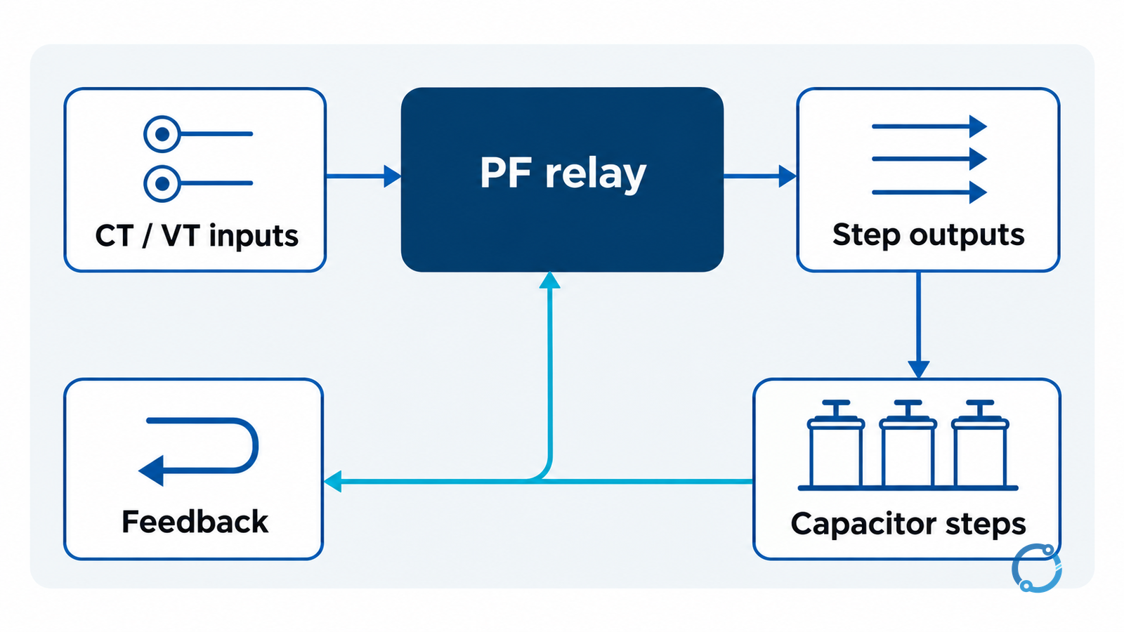
The output side is often where wiring intentions become unclear. A relay may provide:
- step-command outputs to contactors or switching devices;
- alarm or status outputs;
- remote-control inputs;
- a communication interface;
- feedback inputs from contactors or breaker auxiliary contacts; and
- a manual/automatic mode input or selector.
Each output must be treated as an interface with a defined voltage, current, load type, and fail-safe state. A relay contact that is rated for a small pilot load may not be suitable for direct switching of a large contactor coil or a motor-operated device. An interposing relay, contactor, or other interface may be required by the approved design.
The capacitor-bank switching device, step protection, discharge path, and ventilation are not created by the relay. They belong to the power-stage design. The OHELE capacitor-bank panel functional diagram shows how those power and control blocks fit together. The PF relay should be shown as one block within that system, not as the system itself.
LV and MV are different physical boundaries
The measurement and control logic may be described in the same way at LV and MV, but the installation boundary changes:
| Interface | LV panel | MV system |
|---|---|---|
| Voltage input | May be direct or VT-derived | Usually VT-derived, with separation and protection |
| Current input | May be direct or CT-derived | CT secondary with defined shorting and test facilities |
| Relay location | Often within the LV compartment | May be in a separate protection and control compartment |
| Control output | LV contactor or interposing relay | Interface to MV switching device and interlocking scheme |
| Access | Panel-level isolation and verification | Switching, earthing, compartment access, and permit controls |
| Commissioning | Point-to-point checks and functional test | Additional primary/secondary injection, interlock, trip, and remote-control checks |
This table is a planning aid, not a substitute for the site’s electrical safety program. An MV relay may be physically remote from the current and voltage transformers. The wiring route, shielding, separation from power cables, and terminal identification become part of the design. A control cable that is acceptable in an LV panel may not be acceptable for an MV secondary circuit without the required separation and protection.
A six-block commissioning schedule
A useful commissioning record can be organized around six blocks:
- Document identity. Record the relay model, firmware or configuration reference, drawing revision, CT/VT ratios, and approved setting file.
- Measurement inputs. Verify phase assignment, polarity, ratio, burden, test-link state, and the comparison between injected or known values and relay readings.
- Auxiliary supply. Confirm voltage, polarity, protection, changeover behavior, and the effect of a supply interruption.
- Control outputs. Prove each output point to point, verify the commanded device, check feedback, and define the de-energized or fail-safe state.
- Operating modes. Test manual, automatic, remote, local, inhibit, and reset behavior as applicable. Confirm that an operator cannot unknowingly command a step that the power stage cannot accept.
- Restoration and records. Remove test links, restore CT/VT circuits, confirm earths and barriers, record final readings, and sign the handover.
The exact tests depend on the relay and the system. The important discipline is that every wire is proven at both ends, every polarity is recorded, and every output is tested against the device it actually controls.
What the relay does not decide
A PF relay can measure power factor and issue step commands. It does not determine the correct capacitor rating, the permissible harmonic condition, the required detuning, the short-circuit rating of the switching device, or the protection coordination for the bank. Those decisions require the power-system study and the approved equipment design.
The OHELE explanation of why power factor is corrected covers the system-level reason for the control scheme. The MCCB selection guide for APFC panels covers one part of the protection boundary. The MV power-factor correction breaker guide addresses the higher-voltage switching context. Keep those boundaries visible in the drawing so that a relay setting change is not mistaken for a change to the power-stage rating.
Commissioning without guesswork
The safest approach is to commission the relay in stages: verify the drawing and the isolated wiring first, inject or compare measurement values second, prove outputs without the power stage third, and only then proceed to the approved integrated test. The person performing the work must be qualified for the voltage and equipment involved, and the switching procedure must define isolation, verification, earthing where required, and the authority for restoration.
If a reading is wrong, do not correct it by changing an unrelated setting. Trace the measurement chain. If an output operates the wrong device, do not re-label the drawing after the fact. Correct the wiring or the approved design. If a step command produces an unexpected system response, stop the functional test and investigate the power-stage interface, feedback, and control mode.
The bottom line
Power-factor relay wiring is an interface-engineering task. The relay needs a trustworthy voltage reference, a correctly identified and polarized current measurement, a compatible auxiliary supply, and output circuits that are matched to the devices they control. LV and MV systems share the logic but not the physical safety boundary.
Build the package around a terminal-by-terminal schedule: CT and VT ratios, phase and polarity, supply, outputs, feedback, operating modes, and commissioning evidence. Then connect that schedule to the capacitor-bank design and protection study rather than asking the relay to define them. That approach keeps the control scheme understandable, testable, and within its proper scope.