
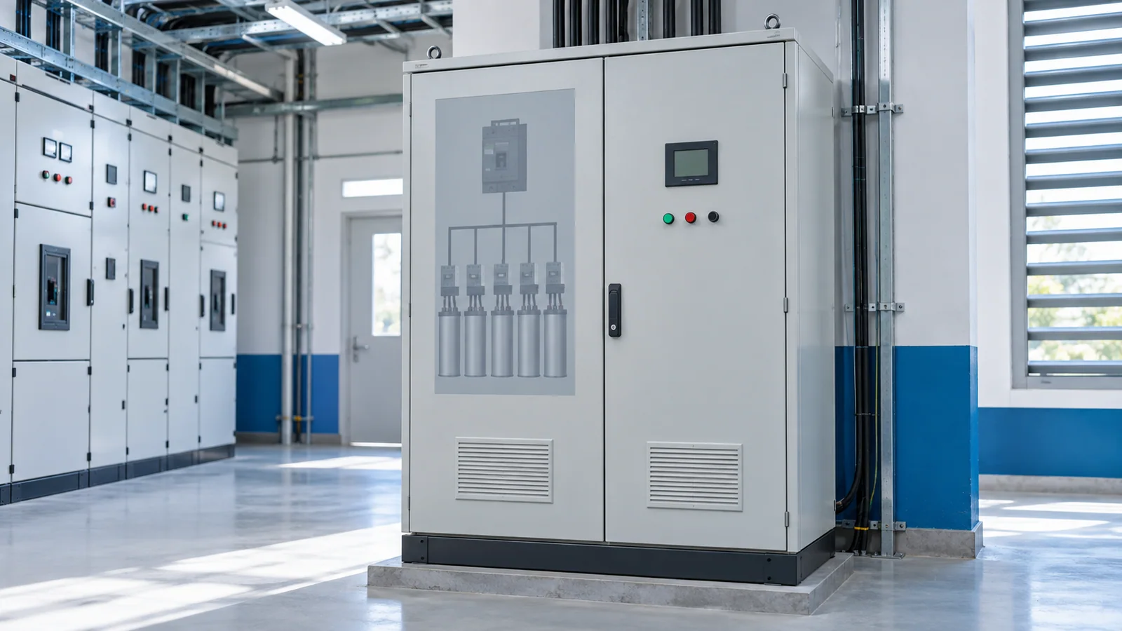
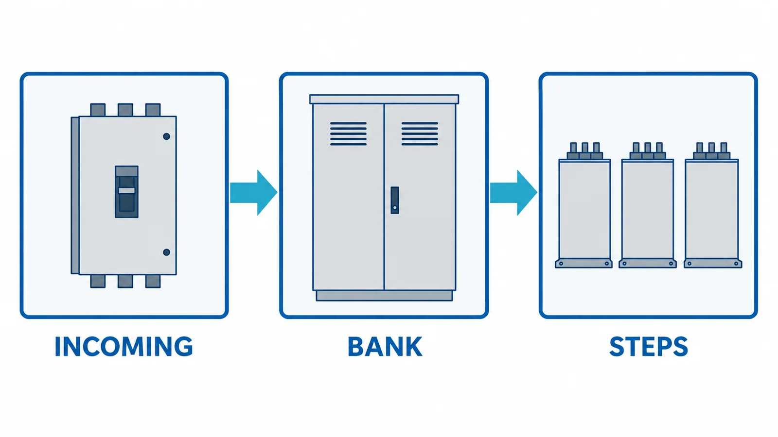
Select the incoming molded-case circuit breaker (MCCB) for an automatic power-factor-correction (APFC) panel from the bank’s maximum operating current, installation fault level, protection/coordination requirements and verified assembly design. A fixed multiple of capacitor nameplate current is not a universal rule: voltage, tolerance, harmonics, detuned reactors, switching arrangements and actual bank configuration can change the duty.
This guide concerns low-voltage AC shunt capacitor banks within IEC 61921:2017, with the breaker considered under IEC 60947-2:2024. It treats the incoming MCCB, not the individual step contactor or step protection. The capacitor unit itself and the panel assembly have separate verification boundaries under IEC 60831-1:2014 and, where applicable, IEC 61439-2:2020.
Establish the bank’s actual current envelope
For a balanced three-phase bank, an initial nominal-current estimate is I = Q / (√3 × VLL), where Q is three-phase reactive power in var and VLL is line-to-line voltage in V. The result is amperes at the stated voltage and nominal operating condition; it is not a breaker rating. For an illustrative 100 kvar bank at 400 V, I ≈ 100,000 / (1.732 × 400) ≈ 144 A. This arithmetic assumes sinusoidal balanced operation and does not include harmonic current, overvoltage, capacitance tolerance or reactor effects. Do not select a 144 A breaker from this single calculation.
| Required input | Selection implication | What to verify |
|---|---|---|
| Installed bank kvar, voltage, steps and reactor topology | Maximum continuous bank current | As-built bank schedule and applicable current envelope |
| Harmonic spectrum and resonance assessment | Additional current/heating and possible detuning need | Power-quality study; do not assume a standard reactor percentage |
| Maximum prospective short-circuit current at incoming terminals | Breaking capacity | Short-circuit study at the actual panel location |
| Conductors, busbars and enclosure temperature | Usable current rating/derating | Cable and assembly design evidence |
| Upstream/downstream protection | Coordination and fault isolation | Exact settings and coordination evidence |
| Switching sequence and step protection | Transient and step-level duty | Dedicated switching devices and step protection design |
Distinguish protection from switching
The incoming MCCB normally provides isolation and protective functions for the bank feeder; it is not the routine switching element for every capacitor step. Step contactors or other purpose-designed switching equipment have their own making/switching duty. Compare the breaker trip settings with the bank’s legitimate operating currents, while preserving conductor and assembly protection. A high instantaneous pickup chosen merely to avoid nuisance trips can leave an unacceptable protection gap. The broader LV selectivity workflow explains how to document coordination across fault-current regions; this APFC article adds the capacitor-bank input set.
What a completed specification should state
Record the exact bank configuration, calculated and measured/assessed current envelope, voltage and frequency, prospective fault current, breaker voltage/current/breaking ratings, release settings, installation derating, upstream coordination, assembly rating and capacitor/step protection evidence. Check the harmonic environment before finalizing current and reactor assumptions. Verify that the applicable IEC and locally adopted editions govern the project; the existence of a standard does not certify a specific panel.
Only qualified designers should finalize protection settings and perform commissioning under local safety procedures. This is a selection worksheet, not a substitute for the bank designer’s verified data.