
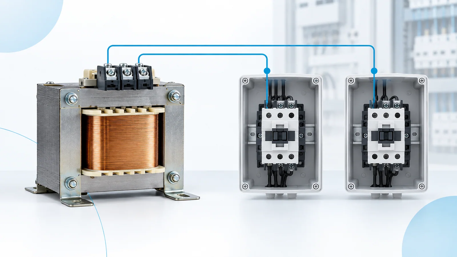
Do not size a contactor control transformer from coil holding VA alone. Build at least two load cases: the largest credible simultaneous pickup demand, and the steady sealed/holding demand. Then verify that the selected transformer’s secondary voltage remains within every coil’s permitted operating range at pickup, including source-voltage and wiring-drop conditions.
This is an IEC-oriented design framework for AC control transformers serving electromechanical contactors. IEC 61558-2-2:2022 addresses safety requirements and tests for control transformers; IEC 60947-4-1:2023 covers relevant electromechanical contactors and starters. Neither catalog page supplies a universal coil inrush value. Use the actual coil and transformer technical data for the final design.
Separate transient and continuous loads
For each device on the control secondary, capture rated control voltage, pickup/inrush apparent power (VA), holding VA, duration or duty where declared, and which other devices can be energized simultaneously. Include pilot lamps, relays, solenoids and other loads—not only the principal contactor. Interlocking logic may prevent two coils from picking up together, but prove that from the control scheme rather than assuming it.
| Load case | Sum these demands | Main verification |
|---|---|---|
| First energization | All loads that can pick up together, plus loads already energized | Secondary voltage at the farthest critical coil during the transient |
| Transfer or restart | Coils that may re-pick up after a supply interruption | Control sequence and available secondary voltage |
| Steady operation | Simultaneous holding VA and continuous auxiliary loads | Thermal/continuous transformer rating and voltage regulation |
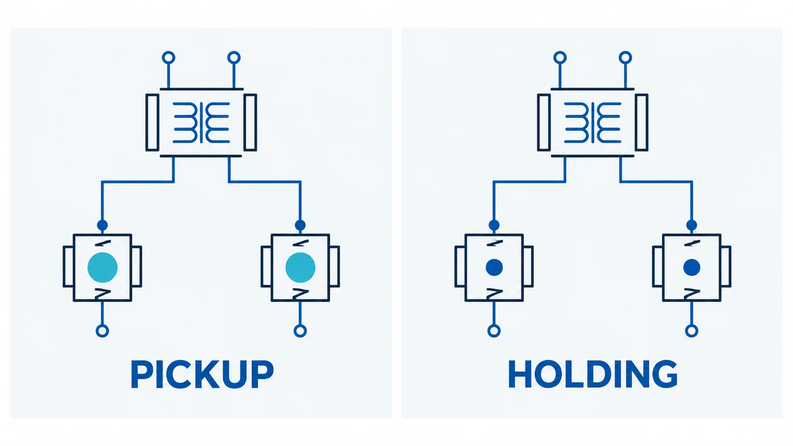
Work through a transparent VA worksheet
Use VA = V × A for a load where its RMS voltage and current are known and the operating state is defined. If a coil’s own documentation gives pickup VA and holding VA, use those state-specific values rather than calculating from a nominal current that may apply to only one state. For the continuous case, add all holding and other continuous VA. For the transient case, add only the pickup VA of coils that truly operate together plus the holding/auxiliary VA already on the secondary. The maximum of those two sums is not by itself the selected transformer size: transformer regulation and allowed short-duration loading must also be checked against the specific transformer’s performance data.
As an illustrative arithmetic example only, suppose one coil has 120 VA pickup and 12 VA holding, another has 80 VA pickup and 8 VA holding, and a pilot/relay load consumes 10 VA continuously. If both coils can pick up together, the transient sum is 120 + 80 + 10 = 210 VA; the steady sum is 12 + 8 + 10 = 30 VA. If interlocking proves sequential pickup, the largest modeled transient may instead be 120 + 8 + 10 = 138 VA, depending on which coil is already sealed. These figures are invented for arithmetic, not product ratings or a transformer recommendation. The appropriate standard size depends on the transformer’s regulation curve, permissible duty, primary variation and wire drop.
Verify the circuit, not just the nameplate
Check primary frequency/voltage, secondary nominal voltage, short-circuit and overload protection, grounding/earthing arrangement, conductor size, terminal voltage at the most demanding coil, panel temperature and any isolation requirement. A transformer can have ample continuous VA while excessive pickup sag prevents a contactor from sealing. Conversely, oversizing without checking protection and installation conditions is not a complete design. Record the simultaneous-load assumption and review it when the control sequence changes.
The breaker-versus-contactor duty guide explains why a contactor’s repeated switching role differs from the protective device that safeguards its circuit. Final component selection and verification belong to a qualified panel designer using current device data and local requirements.