
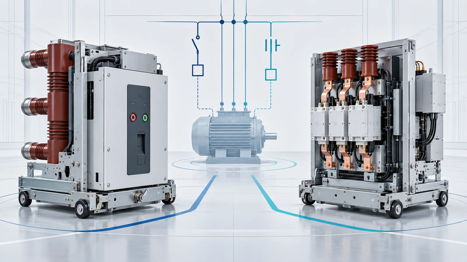
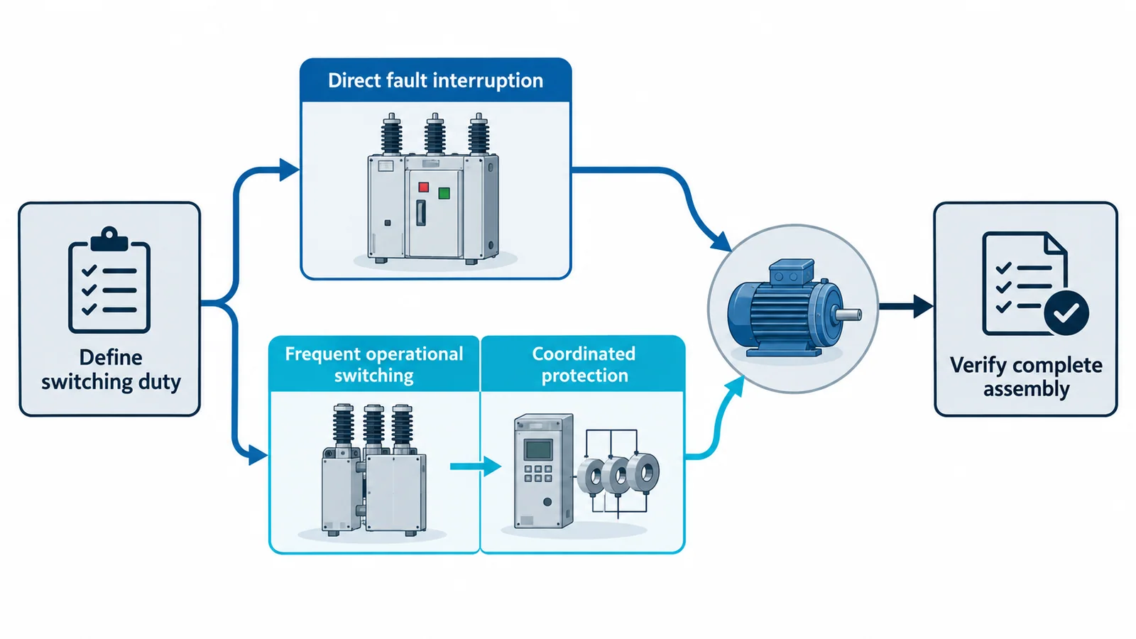
Choose a medium-voltage circuit breaker when the switching device itself must interrupt rated short-circuit current and support broad feeder, transformer, bus or system-protection duties. Choose a contactor-based arrangement when frequent operational switching—often for a motor or process load—is the dominant requirement and a coordinated fuse or circuit breaker provides the required high-level short-circuit protection.
That is a starting rule, not a complete specification. The final choice depends on system voltage, continuous and starting current, load-switching behavior, prospective fault current, operating frequency, required endurance, relay functions, coordination, interlocks and the tested switchgear assembly. Device names alone do not establish capability.
The decision in one table
| Selection question | Circuit-breaker arrangement is usually the stronger starting point when… | Contactor-based arrangement is usually the stronger starting point when… |
|---|---|---|
| Fault interruption | The switching device must directly interrupt the specified prospective short-circuit current | High-level fault interruption is assigned to a coordinated fuse or upstream breaker |
| Operating frequency | Operations are comparatively infrequent or driven mainly by protection and system switching | Repetitive process, motor, reactor or capacitor switching dominates |
| Protection flexibility | Several relay functions, trip logic, reclosing or system-level schemes must act through the device | Motor or process control is primary and the complete starter/controller provides the required protection functions |
| Endurance emphasis | Fault duty and broad application capability outweigh very high operation count | Mechanical and electrical operating life under a defined utilization duty is a central selection input |
| Isolation | A separate disconnector, withdrawable position or assembly-defined isolating function is still evaluated | A separate disconnector, withdrawable position or assembly-defined isolating function is still evaluated |
| Maintenance model | The site supports breaker mechanism, interrupter and trip-circuit inspection appropriate to the design | The site supports contact inspection or vacuum-interrupter assessment, coil/mechanism service and coordinated fuse replacement where applicable |
Neither device should be selected from this table alone. A contactor is not automatically a fault interrupter, and a circuit breaker with an adequate short-circuit rating is not automatically suitable for a high-frequency process duty. For the broader functional boundaries among breakers, switches, disconnectors, earthing switches and fuses, see OHELE’s guide to switching devices in medium-voltage switchgear.
Standards define different equipment scopes
The current IEC documents make the scope boundary explicit:
- IEC 62271-100:2021+A1:2024 applies to three-phase AC circuit breakers for indoor or outdoor installation on systems above 1 kV. Its rating and test framework covers making and breaking duties, not merely continuous current.
- IEC 62271-106:2021 applies to AC contactors, contactor-based controllers and motor starters for indoor installation above 1 kV through 24 kV, at service frequencies up to 60 Hz. It also includes additional requirements for outdoor equipment housed in a protective enclosure.
- IEC 62271-1:2017+A1:2021 provides common specifications for AC switchgear and controlgear above 1 kV unless a product-specific standard states otherwise.
- IEC 62271-200:2021+A1:2024 addresses prefabricated AC metal-enclosed switchgear assemblies above 1 kV through 52 kV. The assembly can change access, isolation, service continuity, partitioning, interlocking and internal-arc considerations.
A device manufactured or tested within one standard’s scope is not automatically suitable for a particular feeder. The declared ratings, tested combination, protection study and assembly documentation must match the actual duty.
Step 1: define the electrical boundary
Record the system before comparing devices:
- highest system voltage and insulation level;
- frequency and grounding method;
- normal and emergency bus configurations;
- maximum and minimum short-circuit current at the feeder;
- X/R ratio or other fault-current characteristics required by the applicable rating method;
- load type and connection arrangement;
- backfeed, regeneration or multiple-source conditions;
- indoor or outdoor service conditions, altitude, temperature, contamination and humidity;
- control supply, trip/close supply and loss-of-control-power behavior.
The prospective fault current is not the load current. It comes from the system short-circuit study and must be checked at the point of installation under credible operating configurations. A feeder device can carry the load comfortably yet still be unsuitable for the available fault duty.
Step 2: calculate the operating current
For a three-phase motor, a useful preliminary estimate is:
I = Pout / (√3 × V × η × PF)
where:
- I is estimated line current in amperes;
- Pout is mechanical output power in watts;
- V is line-to-line voltage in volts;
- η is motor efficiency as a decimal;
- PF is power factor as a decimal.
Use manufacturer or project data when available. The formula does not determine starting current, acceleration time, transient torque, locked-rotor withstand, relay settings or switching capability.
Worked motor-feeder estimate
Assume an illustrative 1 MW, 6.6 kV motor with 96% efficiency and 0.90 power factor at the operating point:
I = 1,000,000 / (√3 × 6,600 × 0.96 × 0.90) ≈ 101 A
The result is only the estimated steady operating current. The selection file must still include:
- starting method;
- starting current and duration;
- starts per hour and minimum time between starts;
- acceleration profile and stalled condition;
- overload and thermal model;
- load-break and making duty;
- fault current and clearing time;
- switching transients and any special capacitor, reactor or transformer duty.
A contactor may be attractive for a frequently started motor, but the complete starter must be coordinated so normal starting does not operate the short-circuit protective device and faults are cleared within the tested combination’s limits. A circuit breaker may simplify direct fault interruption and relay integration, but its permitted operation count and maintenance needs must be checked against the process profile.
Step 3: quantify switching frequency and lifetime operations
Convert the process requirement into comparable numbers. For a repetitive start-stop application:
Annual operating cycles = cycles per operating day × operating days per year
Design-period cycles = annual operating cycles × design years
If the example motor performs 30 start-stop cycles per day for 330 days per year:
Annual cycles = 30 × 330 = 9,900
Over a 20-year design period, before any allowance for commissioning, testing, abnormal process events or changed production demand:
Design-period cycles = 9,900 × 20 = 198,000
Do not compare that number casually with a catalog endurance value. Confirm whether the product counts an operation, close-open sequence or individual opening/closing action; whether the declared endurance is mechanical or electrical; which current and utilization duty applied; and what inspection or component replacement is required during that period.
This calculation often exposes the real decision. Two devices can both carry 101 A and switch the motor, yet only one architecture may fit the forecast operation count without an impractical maintenance burden.
Step 4: assign fault-clearing responsibility
Draw the protection chain from source to load and state which device clears each fault region.
Circuit-breaker feeder
A protection relay or direct-acting function detects the abnormal condition and commands the breaker to open. The breaker must have the applicable making, breaking, short-time withstand, transient recovery voltage and operating-sequence capabilities for the system. Coordination still includes upstream and downstream devices, CT performance, relay timing, arc-flash objectives and breaker-failure consequences.
Contactor-based feeder
The contactor performs normal operational switching. High-level short-circuit interruption is commonly assigned to a coordinated current-limiting fuse or another protective device. The contactor, protective device, relay functions and assembly must be evaluated as a combination. Important questions include:
- What current can the contactor make and break for the stated duty?
- Which fault range is interrupted by the contactor or controller, and which by the fuse or breaker?
- What transfer current or coordination boundary applies to the tested arrangement?
- Will motor starting, transformer inrush or capacitor transients operate the protective device?
- What happens after a single-phase fuse operation or loss of phase?
- Does the protection clear faults before the motor, cable, contactor and switchgear withstand limits are exceeded?
The phrase “contactor plus fuse” is not a substitute for tested coordination. Component ratings viewed separately may not describe the performance of the complete starter.
Step 5: classify the load-switching duty
The same RMS current can represent very different interruption conditions.
Motors
Capture starting current, acceleration time, starts per hour, jogging or plugging, reversing, stalled current, thermal capacity and process interlocks. Frequent closing and opening favor contactor-based control when the coordinated fault-protection architecture is acceptable. Large motors, long starting times, complex protection or system duties may favor a breaker-based feeder even when starting is repetitive.
Transformers
Magnetizing inrush, energization point, sympathetic inrush, protection sensitivity and switching frequency matter. A breaker is commonly the stronger starting point when the feeder also carries system-protection duties. A contactor should not be assumed suitable merely because normal current is low.
Capacitors and reactors
Inrush, outrush, restrike behavior, transient overvoltage and back-to-back switching can dominate. Use the device’s declared capacitive or inductive switching class and the results of the system study. Do not generalize a motor-switching endurance claim to capacitor duty.
Process heaters and resistive loads
Current may be comparatively predictable, but operation count, cold resistance, transformer coupling and process cycling can still control the choice. Semiconductor switching or a hybrid architecture may be a separate solution when cycling is extremely fast; that is outside this article’s breaker-versus-contactor scope.
Step 6: evaluate the complete assembly
The feeder is more than its interrupter. Verify:
- fixed, removable or withdrawable construction;
- isolation and earthing method;
- shutters, interlocks and position indication;
- control circuit supervision and anti-pumping logic where applicable;
- relay, fuse and CT arrangement;
- cable termination and test access;
- service-continuity and partition requirements;
- internal-arc classification when specified;
- room pressure relief and installation conditions;
- remote operation, permissives and process interlocks;
- spare parts, competent maintenance resources and outage strategy.
A contactor’s high operation capability is of limited value if fuse replacement, access or inspection requires unacceptable process downtime. A breaker feeder’s protection flexibility is of limited value if its mechanism and interrupter duty are mismatched to the daily operating cycle.
Selection workflow
- Calculate normal current, but keep starting, inrush and transient duties separate.
- Obtain the fault study for maximum and minimum credible system conditions.
- Forecast operating cycles by day, year and design period.
- Identify the load duty: motor starting, transformer energization, capacitor/reactor switching or another process.
- Assign fault interruption to the breaker, fuse or coordinated combination explicitly.
- Check protection coordination against cable, motor, transformer and switchgear withstand limits.
- Verify device ratings and endurance for the stated current, duty and operating sequence.
- Verify the assembly, including isolation, earthing, interlocks, access and internal-arc requirements.
- Build the maintenance model from the manufacturer’s instructions and actual operation count; do not invent a generic interval.
- Review safety and operating procedures with the asset owner and qualified personnel before commissioning.
Safe operation and maintenance boundary
Selection does not authorize operation or maintenance. Switching instructions must be based on the one-line diagram, equipment design, system state, interlocks, backfeed paths and an approved site procedure. Only trained and authorized qualified personnel should operate or maintain medium-voltage switchgear.
For U.S. electric-power generation, transmission and distribution installations within its scope, OSHA 1910.269 addresses qualified employees, de-energizing, tagging, testing for absence of voltage, grounding and work near exposed energized parts. Applicability depends on the installation and work; other OSHA provisions or local rules may govern industrial utilization equipment.
Good practice includes reviewing remote and automatic closing logic, confirming the intended source and load state, respecting interlocks, controlling the work zone and treating equipment as energized until the applicable de-energizing process is complete. Never defeat an interlock or repeatedly close onto an unexplained trip to restore production.
Data sheet inputs to issue before procurement
| Data group | Minimum information |
|---|---|
| System | voltage, frequency, grounding, insulation level, source configurations |
| Load | type, rated power/current, power factor, efficiency, starting or inrush profile |
| Switching | operations per hour/day/year, duty sequence, minimum idle time, reversing/jogging needs |
| Fault | maximum/minimum fault current, X/R or applicable asymmetry data, clearing objective |
| Protection | relay functions, CT data, fuse/breaker coordination, trip/close supply, breaker-failure philosophy |
| Assembly | fixed/withdrawable arrangement, isolation, earthing, LSC/partition/IAC needs, cable interface |
| Service | indoor/outdoor, altitude, temperature, contamination, humidity, seismic or special conditions |
| Lifecycle | design years, forecast cycles, maintenance capability, spares, outage constraints |
If these inputs are missing, postpone the device decision rather than filling the gaps with a generic breaker or contactor rating.
Bottom line
The practical choice between a medium-voltage circuit breaker and contactor starts with two questions: who must interrupt the fault, and how often must the load be switched? A circuit breaker is generally the stronger starting point for direct fault interruption and broad system-protection duties. A contactor-based arrangement can be the stronger choice for frequent motor or process switching when its coordinated short-circuit protection and complete assembly are suitable.
Calculate operating current, forecast lifetime cycles, classify the load duty, assign every fault-clearing responsibility and verify the tested assembly. That produces a defensible specification; comparing device names or continuous-current ratings does not.
References
- IEC 62271-1:2017+A1:2021 — Common specifications for AC switchgear and controlgear above 1 kV
- IEC 62271-100:2021+A1:2024 — Alternating-current circuit breakers
- IEC 62271-106:2021 — AC contactors, contactor-based controllers and motor starters
- IEC 62271-200:2021+A1:2024 — AC metal-enclosed switchgear above 1 kV through 52 kV
- OSHA 1910.269 — Electric power generation, transmission and distribution