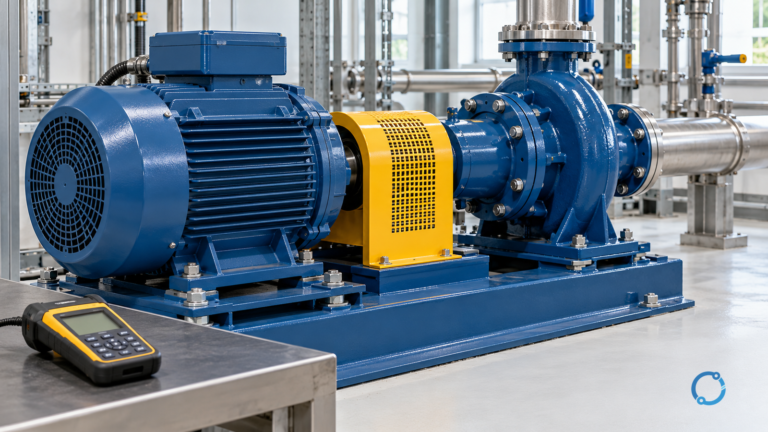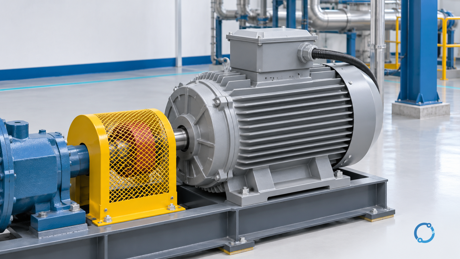
Induction motor slip is the rotor’s shortfall behind the rotating magnetic field. First calculate the field’s synchronous speed in revolutions per minute (rpm):
Ns = 120 x f / P
Then calculate percent slip from a measured rotor speed:
slip (%) = (Ns - Nr) / Ns x 100
Here, Ns is synchronous speed in rpm, f is supply frequency in hertz, P is the total number of magnetic poles, and Nr is measured rotor speed in rpm. The U.S. Department of Energy’s Fundamentals Handbook gives both equations in its AC-motor-theory chapter.
Slip exists because an induction rotor needs relative motion with respect to the rotating stator field to induce rotor current and produce torque. If the rotor reached exactly the field speed, that relative motion and the induced rotor current would disappear in the ideal model described by DOE.
Inputs you need before calculating
| Input | What to verify | Unit |
|---|---|---|
Supply frequency f |
Actual supply or drive output frequency, not an assumed regional value | Hz |
Pole count P |
Total magnetic poles from the motor winding; use an even number such as 2, 4, 6 or 8 | poles |
Measured speed Nr |
Rotor or shaft speed at the operating condition being examined | rpm |
| Nameplate full-load speed | Useful for orientation, but not a substitute for the measured speed | rpm |
Do not use the nameplate rated output power as P. In the synchronous-speed equation, P means pole count. Mixing those two meanings is a common cause of an impossible result.
Synchronous-speed lookup
The table below reproduces the pole and frequency combinations listed in Table 5-1 of the DOE motor-systems guidebook. It gives the rotating-field speed, not a guaranteed shaft speed.
| Poles | 60 Hz synchronous speed | 50 Hz synchronous speed |
|---|---|---|
| 2 | 3,600 rpm | 3,000 rpm |
| 4 | 1,800 rpm | 1,500 rpm |
| 6 | 1,200 rpm | 1,000 rpm |
| 8 | 900 rpm | 750 rpm |
| 10 | 720 rpm | 600 rpm |
| 12 | 600 rpm | 500 rpm |
For example, a four-pole motor on a 50 Hz supply has Ns = 120 x 50 / 4 = 1,500 rpm. Its shaft will run slightly slower when it is carrying an induction-motor load.
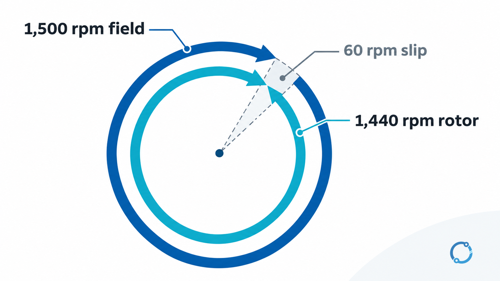
Worked example: 50 Hz, four poles, 1,440 rpm
Assume a four-pole induction motor is supplied at 50 Hz and a tachometer measures 1,440 rpm at the operating point. These are teaching inputs, not a test result.
- Calculate synchronous speed:
Ns = 120 x 50 / 4 = 1,500 rpm. - Find the speed difference:
1,500 - 1,440 = 60 rpm. - Divide by synchronous speed and convert to percent:
60 / 1,500 x 100 = 4.0%.
The slip at that operating point is 4.0%. DOE’s handbook gives a separate 60 Hz example: a two-pole motor has Ns = 3,600 rpm; at 3,554 rpm, (3,600 - 3,554) / 3,600 x 100 = 1.2778%, which DOE rounds to 1.3%.
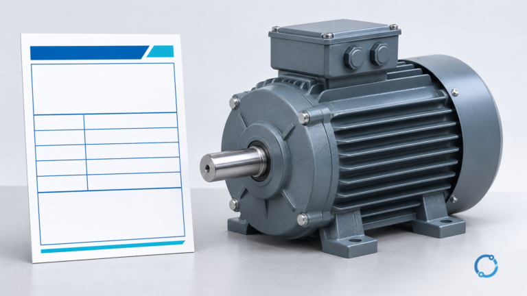
What the nameplate speed can and cannot tell you
A nameplate full-load speed is lower than synchronous speed because slip occurs at rated load. It helps identify the expected speed range, but it is not a measured speed at another load or voltage. DOE’s guidebook says slip varies with load and voltage and that speed-based load estimation is sensitive to tolerance in the reported nameplate full-load speed.
The guidebook describes a slip-based motor-load estimate that compares measured slip with nameplate slip. It also states that the method lacks accuracy, is generally not recommended for determining motor loads in the field, and should be used only when voltage and operating-speed measurements are available. The largest uncertainty it identifies is a 20% tolerance in reported nameplate full-load speed; a small 5 rpm rounding error can substantially change a calculated load. Use input-power measurement instead when a defensible load value is needed.
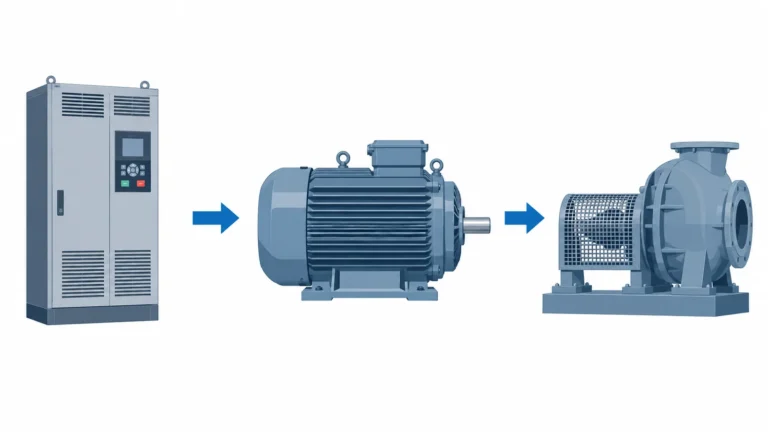
Slip on a variable-frequency drive
The same equations apply to the frequency actually supplied to the motor. At a constant number of poles, reducing supply frequency reduces synchronous speed. A VFD changes supply frequency to vary speed, so using the fixed line frequency while the drive operates at another frequency will produce the wrong Ns.
For a four-pole motor at 30 Hz, for instance, Ns = 120 x 30 / 4 = 900 rpm. That number is the field-speed reference; percent slip still requires a measured rotor speed at the same operating condition. A drive’s displayed output frequency and a separate speed measurement are better inputs than an assumed 50/60 Hz value.
Common calculation checks
- Frequency is in Hz, not rpm; poles are a count, not power.
NsandNrare both in rpm before division.- Slip is dimensionless; multiplying by 100 gives percent.
- A negative result means the measured speed is above the calculated field speed; recheck frequency, pole count and measurement condition.
- A motor driven above its base frequency, a generator operating condition or a different machine type needs a different analysis. This calculation is for the induction-motor motoring condition described here.
Sources
- DOE Fundamentals Handbook, Electrical Science, Volume 4: AC Motor Theory, Slip, Equations 12-1 and 12-2.
- DOE Continuous Energy Improvement in Motor Driven Systems: Synchronous Speed; The Slip Method; Table 5-1; Equations 5-5 and 5-6.
- OHELE: Induction Motor Calculations Every VFD User Should Know.