
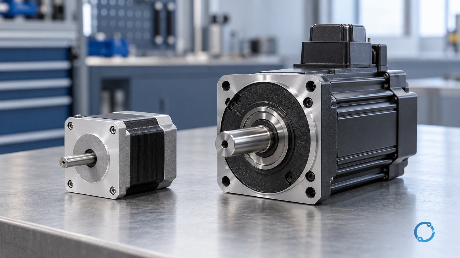
Choose a stepper axis when its verified torque-speed curve and thermal duty cover the complete motion profile, and the application can tolerate its chosen position-verification strategy. Consider a servo axis when the machine needs controlled feedback, dynamic response or recovery behavior that a suitable servo system can provide. Neither name alone proves that the axis will reach position, hold a load safely or meet an accuracy requirement.
The fair comparison is between two complete axes: motor, drive, supply, controller, feedback where used, transmission and load. The motor must be assessed at the speed, acceleration, ambient temperature and duty at which the machine actually operates.
What each term describes
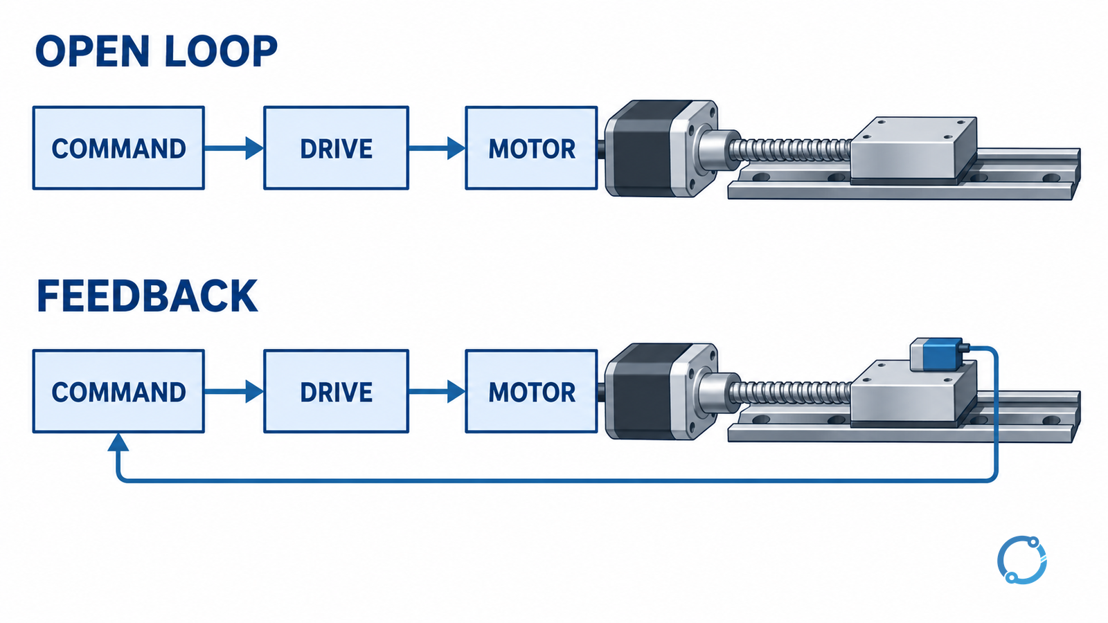
A stepper motor advances its magnetic field in commanded increments. A suitable drive sequences winding current; a controller plans the motion. In an open-loop installation, the controller’s commanded position is not necessarily the actual load position. If the load prevents the rotor from following, the command count alone cannot reveal the error. Some stepper systems include feedback and correction or fault detection; their implementation differs between drives.
Servo describes a feedback-controlled motion system rather than one unique motor construction. A typical industrial servo axis combines a motor, power drive, sensor and controller to regulate position, speed or torque. Feedback can reveal a following error and support a configured response, but it does not automatically prove the load itself is correctly positioned. A motor encoder upstream of a belt, coupling or gearbox cannot see every downstream failure.
Compare the same job, not just catalog labels
| Decision dimension | Stepper axis | Servo axis | Evidence to request |
|---|---|---|---|
| Available torque | Compare the complete drive-specific speed–torque curve with the trajectory, not only holding torque. | Compare continuous and peak capability with the trajectory and allowed duration. | Curves at actual supply and drive settings. |
| Position evidence | Open loop counts commands; optional feedback may detect or correct error. | A closed control loop uses feedback, but its sensor location matters. | Sensor location, resolution, following-error and fault behavior. |
| Motion and settling | Discrete excitation and machine resonance can affect smoothness; microstepping may improve command granularity. | Tuning and mechanical resonance influence stability and settling. | Measured performance on the actual load, not command resolution alone. |
| Standstill and heat | Holding current and duty can heat the motor and drive. | Holding and continuous torque draw depend on the drive, load and thermal limits. | Continuous duty, ambient and mounting conditions. |
| Integration | Simpler command paths can be appropriate when assumptions remain valid. | Additional feedback and tuning may be justified by the performance requirement. | Interface, diagnostics, commissioning effort and spares. |
| Power loss and restart | Holding torque is not a safety-rated brake. | Feedback and controlled torque are not, by themselves, a safety function. | Risk assessment, vertical-load restraint and restart sequence. |
These are evaluation questions, not universal rules. Actual products can overlap. A closed-loop stepper and a servo drive may have different correction and fault strategies even when both use encoders.
Start with the load and trajectory
Define the mass or inertia seen at the motor, the transmission ratio, peak speed, acceleration, deceleration, direction changes, external forces and friction. Include the required dwell and repeat cycle. If the load changes with product, position or temperature, evaluate the limiting cases rather than one average point.
For a rotating load, an initial rigid-body estimate is T = J × α, where torque T is in newton-metres, equivalent inertia J in kilogram-square-metres, and angular acceleration α in radians per second squared. Add torque needed for external load, friction and transmission losses; use the sign appropriate to acceleration and deceleration. Reflected inertia depends on the transmission ratio and must be calculated consistently at the motor shaft.
For illustration only, if the motor-side equivalent inertia is 0.004 kg·m² and the requested acceleration is 50 rad/s², the acceleration component is 0.20 N·m. If the other motor-side demand is independently estimated as 0.30 N·m in the same direction, the instantaneous total is about 0.50 N·m before uncertainty and additional losses. This is not a motor rating or a complete axis design. Plot the demand against speed through the move, check peak duration and calculate the thermal duty for the full cycle.
For further load mapping, see motor and VFD sizing for machine loads. A VFD-driven induction motor and a precision positioning axis have different control objectives; the shared starting point is the real mechanical duty.
Read torque at operating speed
Holding torque describes a stationary condition under the stated conditions. It cannot establish torque available during a fast move. For a stepper, use the curve for the proposed motor, drive, supply and current setting; available running torque generally changes with speed. Include acceleration through the entire range and any resonance or start-stop restrictions specified for the axis.
For a servo, separate continuous torque from short-duration peak torque. A motor may deliver a peak only within the drive’s current, thermal and timing constraints. A move that repeatedly needs peak torque may exceed the continuous duty even though a single move succeeds. Evaluate regenerative energy during deceleration as well as acceleration and check the drive and supply can handle it.
Both candidates need margin for uncertainty, load variation and aging. The amount is an engineering decision based on verified data and the consequences of a missed move; a universal percentage is not a substitute for analysis.
Separate command resolution from actual accuracy
Microstepping creates finer commanded current increments, but finer increments do not guarantee proportionately finer load accuracy. Friction, load torque, magnetic and mechanical variation, compliance and backlash affect the actual position. Likewise, encoder counts are only one component of a servo axis’s positioning uncertainty.
Specify separately:
- Resolution: the smallest distinguishable command or feedback increment in the stated system.
- Accuracy: closeness of the actual load position to its target under defined conditions.
- Repeatability: spread of repeated approaches under defined conditions.
- Settling: time and tolerance band after a move, including any residual oscillation.
- Following error: difference between command and measured position at the chosen sensor.
Identify the point being measured: motor shaft, screw or working tool. A high-resolution motor encoder does not remove belt stretch, screw pitch error or coupling slip. If the end process demands direct load verification, assess an appropriate load-side sensor and its integration.
Check feedback, homing and lost-position behavior
An open-loop stepper relies on the motor tracking commanded steps. Determine what happens after a stall, power interruption or manual movement, and how the machine establishes a known position again. A home sensor and a controlled homing procedure can establish a reference, but do not continuously prove position between checks.
A feedback axis must define the error it detects and the response: controlled stop, fault, alarm or permitted correction. The answer depends on the controller, sensor, drive configuration and machine risk assessment. Closed-loop stepper implementations are not all identical, and a servo that reaches its motor encoder target may still have a downstream mechanical fault.
Consider what happens if a sensor fails, an encoder cable is disconnected, the drive loses supply or the load moves while the axis is disabled. Confirm the actual diagnostic coverage with the system documentation. Fault detection is not automatically a safety-rated function.
Duty, resonance and environment
Calculate heating over the full cycle, including holding, repeated acceleration and time at low speed. Mounting surface, enclosure, ventilation and ambient temperature affect the installed thermal result. Check the motor and drive documentation for permitted continuous and intermittent operation. If temperatures rise unexpectedly, investigate the actual load and cooling conditions using the motor temperature diagnostic guide.
Any mechanical system has modes that can respond to a motion profile. A stepper can show resonance at certain speeds, while a poorly tuned feedback system can oscillate or become unstable. The cure is not to assume one technology is immune: assess the mechanical stiffness, load, controller configuration and permitted test method. Use controlled commissioning and the manufacturer’s limits rather than applying unverified settings.
Noise and vibration requirements should be tested on the assembled machine. Gearing, mounting, structural panels and the load can dominate what an operator hears, regardless of motor type.
Safety and total system cost
For a vertical axis or stored-energy load, neither energized holding torque nor an ordinary position loop is a substitute for the required load restraint. Assess brake selection, gravity, stored mechanical energy, power failure, restart, guarding and emergency functions for the whole machine. A drive’s control mode or feedback sensor should not be described as safety-rated without the specific system evidence.
Only qualified and authorized people should install, test or service the equipment. Use the site energy-control procedure and account for electrical, mechanical and stored energy before access. In the United States, OSHA’s general-industry hazardous-energy rule has a defined scope and exceptions; electrical work and other jurisdictions can have additional requirements.
Compare the complete lifecycle: drive, motor, feedback, power supply, transmission, wiring, commissioning, training, diagnostic coverage, downtime and spares. A lower initial motor price is not a complete axis cost. Conversely, added feedback and tuning may offer little value when a simpler verified solution meets the documented duty and failure consequences.
A practical selection record
- Document the load, full motion profile, travel, duty cycle and environmental limits.
- Specify load-side accuracy, repeatability, settling and permitted following error separately.
- Calculate motor-side demand and compare it with candidate curves and thermal limits at actual drive settings.
- Define homing, feedback location and the response to a stall, sensor fault or lost power.
- Check transmission, mounting, noise, braking and machine safety functions.
- Commission the complete guarded axis under an approved test plan, record results and resolve deviations before release.
An axis is selected when its documented capability covers the required duty and its failure response is acceptable for the application. IEC 60034-1 addresses ratings and performance of rotating electrical machines within its scope; a catalog reference alone does not establish compliance of an assembled machine.
Sources
- IEC, IEC 60034-1:2026, Rotating electrical machines — Rating and performance, official publication page linked above.
- OSHA, The control of hazardous energy, 29 CFR 1910.147, linked above; applicable U.S. general-industry scope must be checked.