
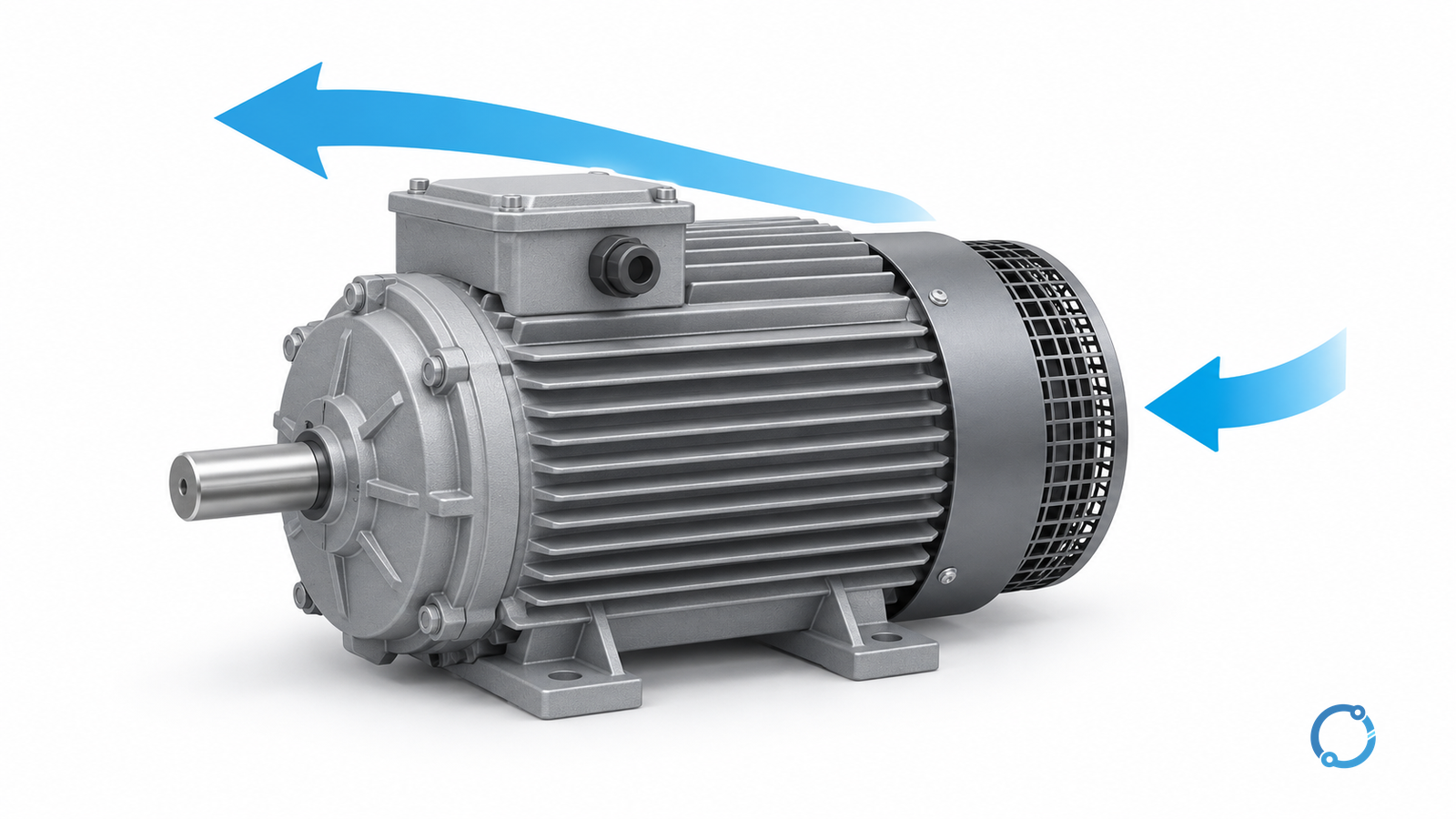
Interpret a motor-temperature change by first identifying what was measured and under what conditions. A hotter frame, a higher winding-sensor reading and a warmer bearing are different observations. Each needs its own comparison and accepted limits.
This is a diagnostic workflow for industrial induction motors, including converter-fed operation where applicable. It does not provide a universal stop temperature, predict remaining life from one reading or authorize exposed energized inspection.
Establish the measurement boundary
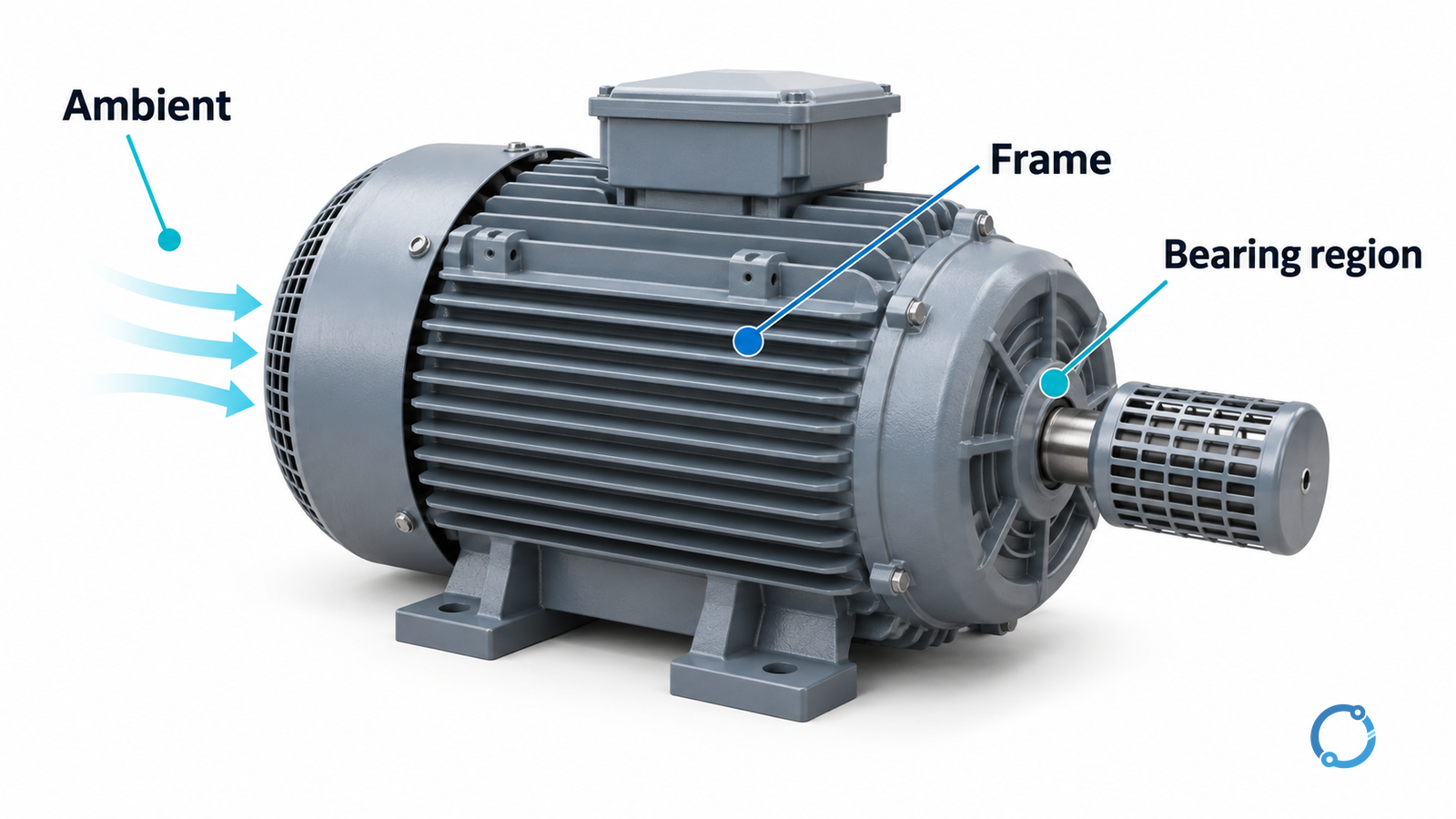
Record the sensor or instrument, location, measurement method, load, speed, run duration, inlet ambient and cooling condition. Compare like with like before naming a cause.
| Observation | What it represents | What it cannot establish alone |
|---|---|---|
| Exterior-frame temperature | Surface at a defined location | Internal winding hotspot or bearing condition |
| Winding sensor | Temperature represented by that sensor and location | Every part of the winding or all insulation stresses |
| Bearing observation | Defined bearing-region or sensor temperature | Lubricant condition or mechanical cause without other evidence |
| Ambient reading | Air at its recorded location | The motor’s actual inlet condition if measured elsewhere |
A thermal camera reports a surface measurement affected by its measurement setup. The National Institute of Standards and Technology (NIST) thermography methodology addresses calibration, emissivity and related measurement issues; it is not a motor alarm-limit table.
Do not translate the color of a thermal image into an insulation-class judgement. Establish the measurement settings and the permitted comparison first.
Separate absolute temperature from rise
When the method and accepted basis permit a comparison, temperature rise is measured component temperature minus its defined ambient. This arithmetic does not turn an external-frame measurement into a winding measurement.
Consider hypothetical comparable winding-sensor records: 95°C with inlet ambient 25°C, then 105°C with inlet ambient 35°C. Both differences are 70°C. The absolute temperature rose 10°C, but the arithmetic alone does not demonstrate increased heat generation.
It also does not prove everything is acceptable. Absolute temperature, sensor location, ambient capability, duty and equipment limits still matter. If the component readings or ambient positions differ, the comparison is not yet valid.
Follow the cause, not the highest color
The U.S. Department of Energy (DOE), in its motor-life tip sheet, identifies voltage conditions, harmonics, ambient, ventilation and loading as overheating contributors. Temperature alone does not distinguish them or establish a specific remaining service life.
| Pattern under comparable conditions | Follow-up evidence | Possible action after cause confirmation |
|---|---|---|
| Broad temperature increase with warmer inlet air | Actual inlet history and permitted ambient/duty | Restore accepted environmental conditions or review capability |
| Increase after contamination or airflow change | Guarded cooling-path condition and maintenance history | Planned isolated cleaning or ventilation correction |
| Increase during a changed load cycle | Shaft duty, current and repetition records | Resolve overload/process change; reassess motor duty |
| Rise during sustained low-speed operation | Speed, cooling arrangement and accepted torque duty | Review motor/converter cooling capability |
| Local bearing-region change with other mechanical symptoms | Qualified bearing, lubrication, alignment and load assessment | Cause-specific maintenance, not arbitrary relubrication |
| Different phases or abnormal electrical history | Qualified supply/current assessment | Correct the supported supply or circuit issue |
The table identifies hypotheses, not a diagnosis from sound, touch or a single thermogram. A protective trip, rapid unexplained change or other evidence of a serious fault needs the site’s immediate escalation procedure; do not repeatedly restart to collect a better trend.
Review cooling when speed or cleanliness changes
DOE’s motor application handbook describes the heat-removal effects of dirt and the reduced airflow of shaft-driven fans at low speed. Less shaft output does not automatically mean adequate cooling.
For a converter-fed motor, use the accepted torque/speed duty and actual cooling arrangement. The motor and variable-frequency drive (VFD) sizing guide addresses that capability review. The VFD selection checklist provides the related converter-interface task.
Do not remove guards, open a terminal box or direct an improvised blower at an operating motor as a diagnostic shortcut. Physical cleaning and repair require the appropriate isolated work state and approved methods.
Use trends without inventing a life clock
Keep a baseline tied to load, speed and environmental conditions. Compare the same sensor and method over time, and record unavoidable differences instead of silently treating unlike readings as equivalent.
A higher insulation thermal class is not evidence that the current operating condition is healthy. Nor should a broad thermal-aging rule be converted into “hours remaining” for a particular motor. Electrical, mechanical and environmental stresses need their own evidence.
Where insulation assessment is justified, the insulation-resistance guide establishes the separate test-boundary task. An isolated electrical test does not directly replace the temperature record.
Close with a verified corrective path
Measurements involving electrical exposure require qualified personnel, appropriate instruments and the site’s approved risk controls. The U.S. Occupational Safety and Health Administration (OSHA), in 29 CFR 1910.333, supplies a work-practice reference, not permission to bypass isolation or protection.
Record the observed change, valid comparison, supported cause, accepted correction and verification condition. Recheck under an agreed equivalent duty and retain the new baseline. The investigation ends when the cause and operating acceptance are resolved, not merely when a display number falls.