
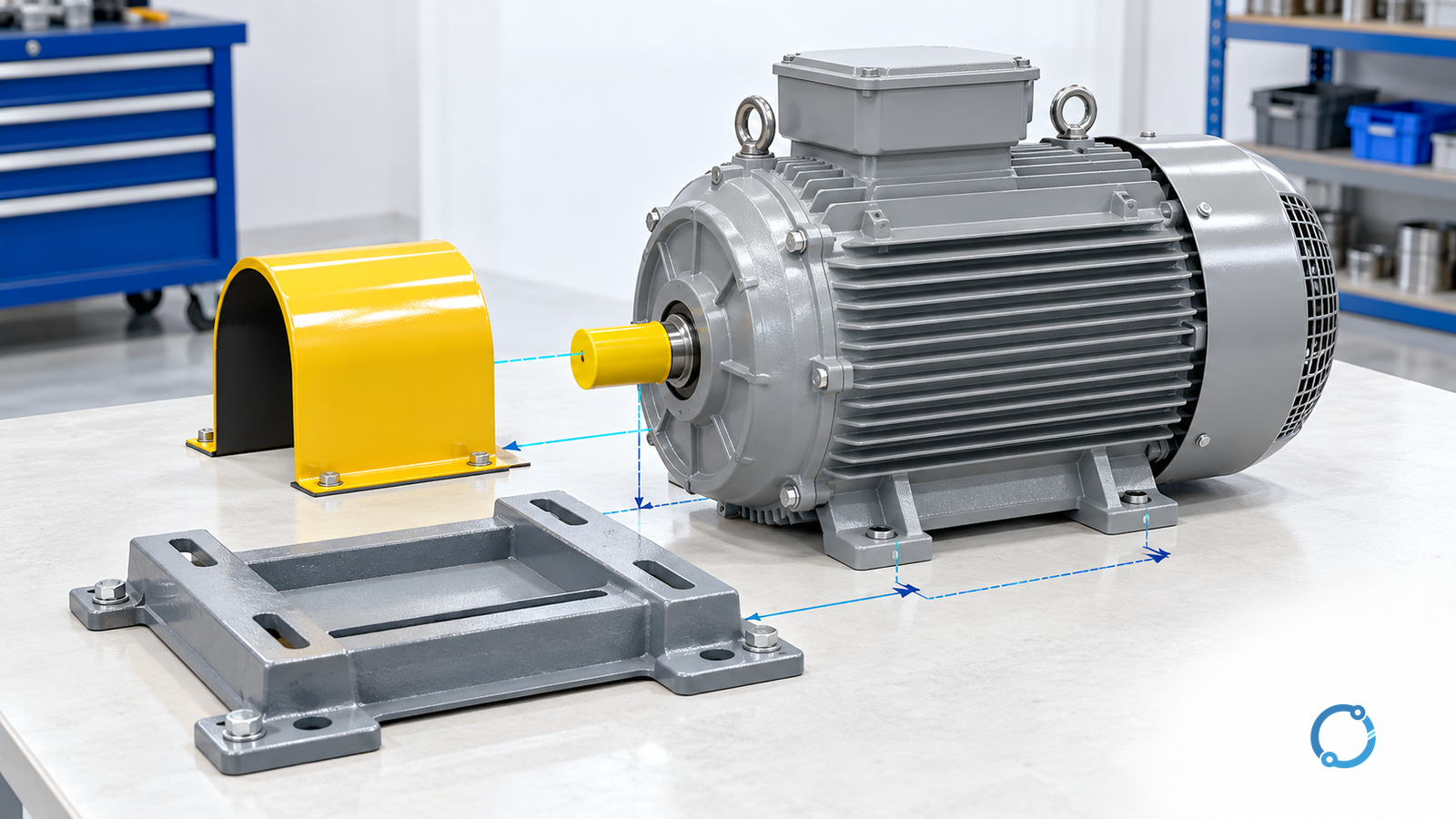
Select a replacement three-phase squirrel-cage induction motor by checking the retained machine’s interfaces, not just matching its kilowatt rating. Mechanical fit, operating speed, starting behavior, cooling and control compatibility can each reject an otherwise plausible substitute.
This workflow concerns replacement of an existing industrial low-voltage squirrel-cage motor. Converting a direct-current, synchronous or wound-rotor installation is a wider system redesign, not an automatic drop-in replacement. The result here is a documented compatibility decision for the existing machine.
Establish what the old motor actually did
Record the machine’s required output, load cycle, actual supply, starting arrangement and environment. Keep the old nameplate information, installation drawing and observed operating condition separate. An unreadable nameplate is a missing input; it does not justify reconstructing ratings from housing size.
Do not assume a failed motor was correctly selected. Identify the reason for replacement and unresolved failure causes before repeating the old specification. A replacement that inherits inadequate ventilation, excessive starts or an unsuitable driven load can inherit the same problem.
The U.S. Department of Energy (DOE), in its replacement-motor fact sheet, identifies actual load, efficiency at that load and existing/replacement loaded speed as relevant inputs. Its legacy software examples are not current product recommendations.
Use the motor and variable-frequency drive (VFD) sizing workflow if the retained machine’s duty is unknown or has changed. That is a prerequisite study, not a reason to guess a larger motor.
Compare five interfaces on the same basis
| Interface | Compare old installation with candidate | Hold the replacement when |
|---|---|---|
| Mechanical | Mounting, shaft, coupling, bearing loads, position and access | A dimension or supported load is unknown |
| Supply | Voltage, frequency, connection arrangement and supply capability | Ratings or connection basis do not match |
| Process | Loaded speed, torque across speed, acceleration and stopping duty | Matching kW hides a different machine result |
| Thermal/environmental | Cooling, ambient, duty, exposure and enclosure suitability | Capability is asserted only at other conditions |
| Controls/protection | Starter or converter, sensors, protection and command behavior | Existing settings or interfaces are assumed suitable |
Use exact candidate drawings and operating data for these comparisons. A frame designation helps organize the review but cannot verify every flange, shaft extension, terminal-box position or bearing arrangement. Similar appearance is particularly weak evidence when mixing different dimensional conventions.
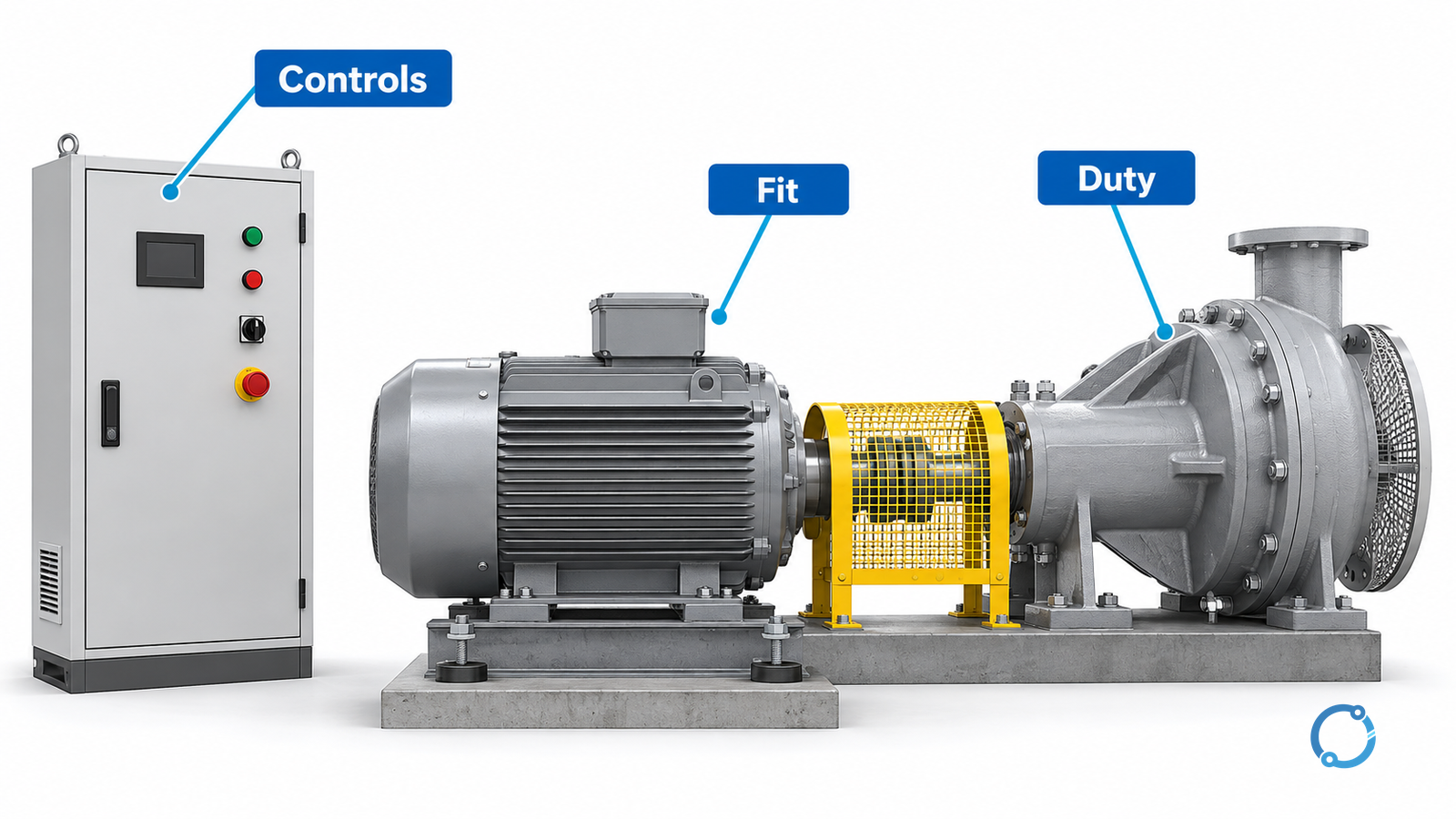
Check loaded speed before calculating savings
Two motors with the same frequency and pole count can have different loaded speeds. Use the induction-motor calculation reference to distinguish synchronous speed, slip and shaft speed.
For a hypothetical similar fan operating point, compare 1,470 rpm with 1,485 rpm. If the relevant affinity-law assumptions hold, the speed ratio is 1,485/1,470 = 1.0102 and the shaft-power ratio is that value cubed, approximately 1.0309. The illustrative power increase is about 3.09%.
This is not measured energy consumption or a universal pump rule. It assumes comparable fluid conditions and operating points; system curves, static head, control changes and efficiency can change the actual result. DOE’s motor application handbook explains why replacement speed deserves attention. Its historic efficiency-regulation tables should not be used as current legal requirements.
An efficiency improvement and a process-speed change are separate effects. Estimate annual savings only after the delivered machine duty is held equivalent or its change is explicitly included.
Retain the starter only after reviewing its duty
Check the candidate’s starting torque/current behavior, acceleration time, permitted starts and load inertia against the retained starter and source. A motor that runs satisfactorily once at speed may still fail the starting duty.
For a VFD, establish the supported motor/converter combination, speed range and cooling arrangement. The International Electrotechnical Commission (IEC), in IEC TS 60034-25:2022, addresses alternating-current machines used with converters and their interaction. Its public scope is not approval of an arbitrary combination.
Reassess thermal protection and sensing against actual candidate data. Do not retain or raise overload settings simply because the new motor fits. The motor-protection circuit-breaker guide covers the separate coordinated protection task.
Close the replacement record before restoration
Keep a disposition for each interface: accepted with evidence, rejected, or unresolved with a named owner. Record any coupling, mounting, control, protection or process change rather than labeling the entire job “like-for-like.”
Physical replacement and verification require authorized personnel and the site’s electrical and mechanical isolation procedures. The U.S. Occupational Safety and Health Administration (OSHA), in 29 CFR 1910.333, provides an electrical work-practice boundary. It does not replace the machine’s safe-work plan.
Plan restoration checks for the agreed supply, rotation, alignment, guarded operation, machine output, current, temperature and protective functions. Select limits and methods from the approved equipment basis, not this generic list. Release the substitution when the retained interfaces and actual duty are accepted, with a new baseline for subsequent maintenance.