
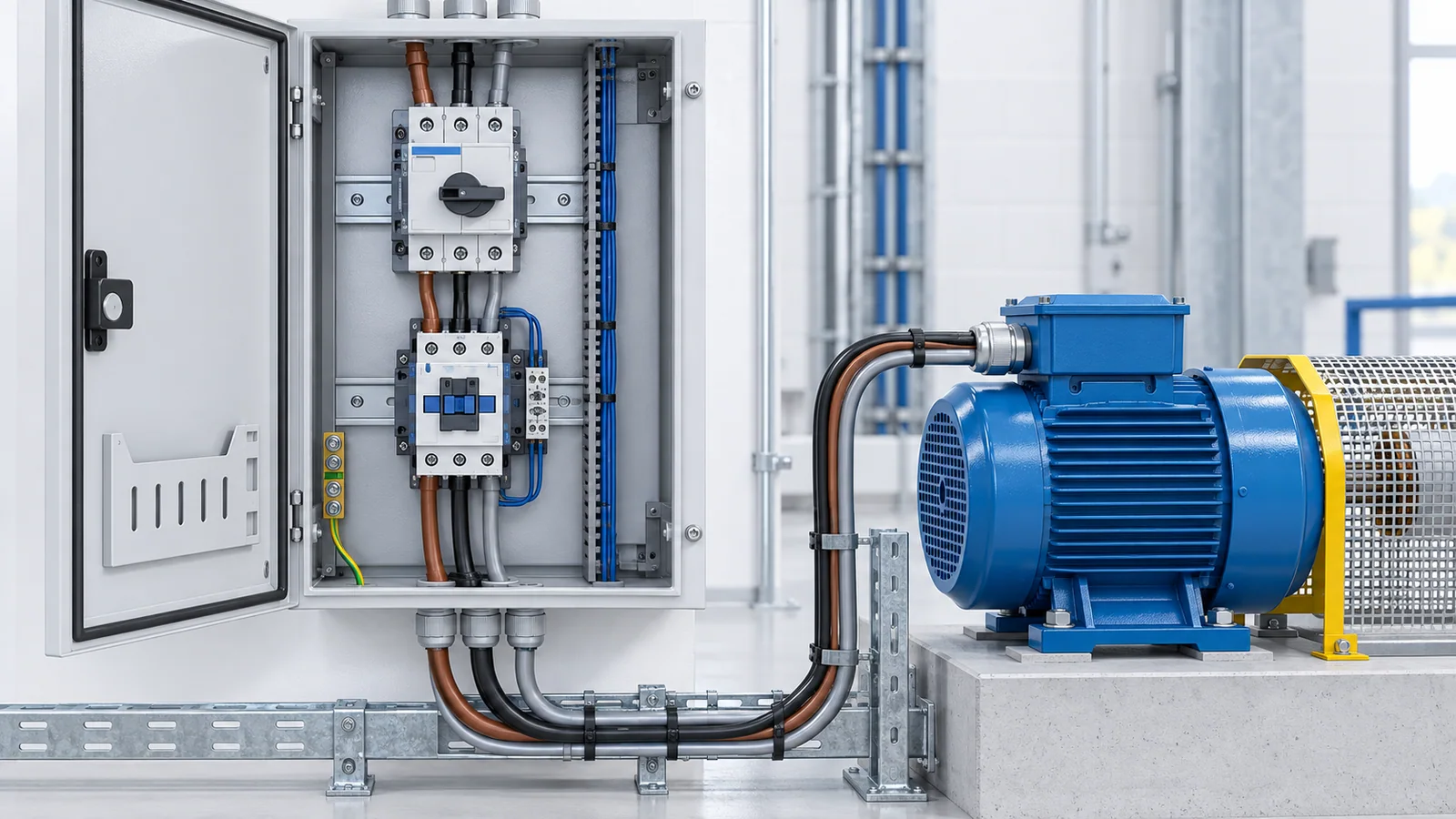
A motor protection circuit breaker (MPCB) is a low-voltage switching and protective device designed around motor-circuit behavior. It typically provides adjustable overload protection, rapid short-circuit protection, and manual switching in one device. Depending on the exact product standard and certification, it may also be called a motor-protective switching device, manual motor starter, or self-protected combination motor controller.
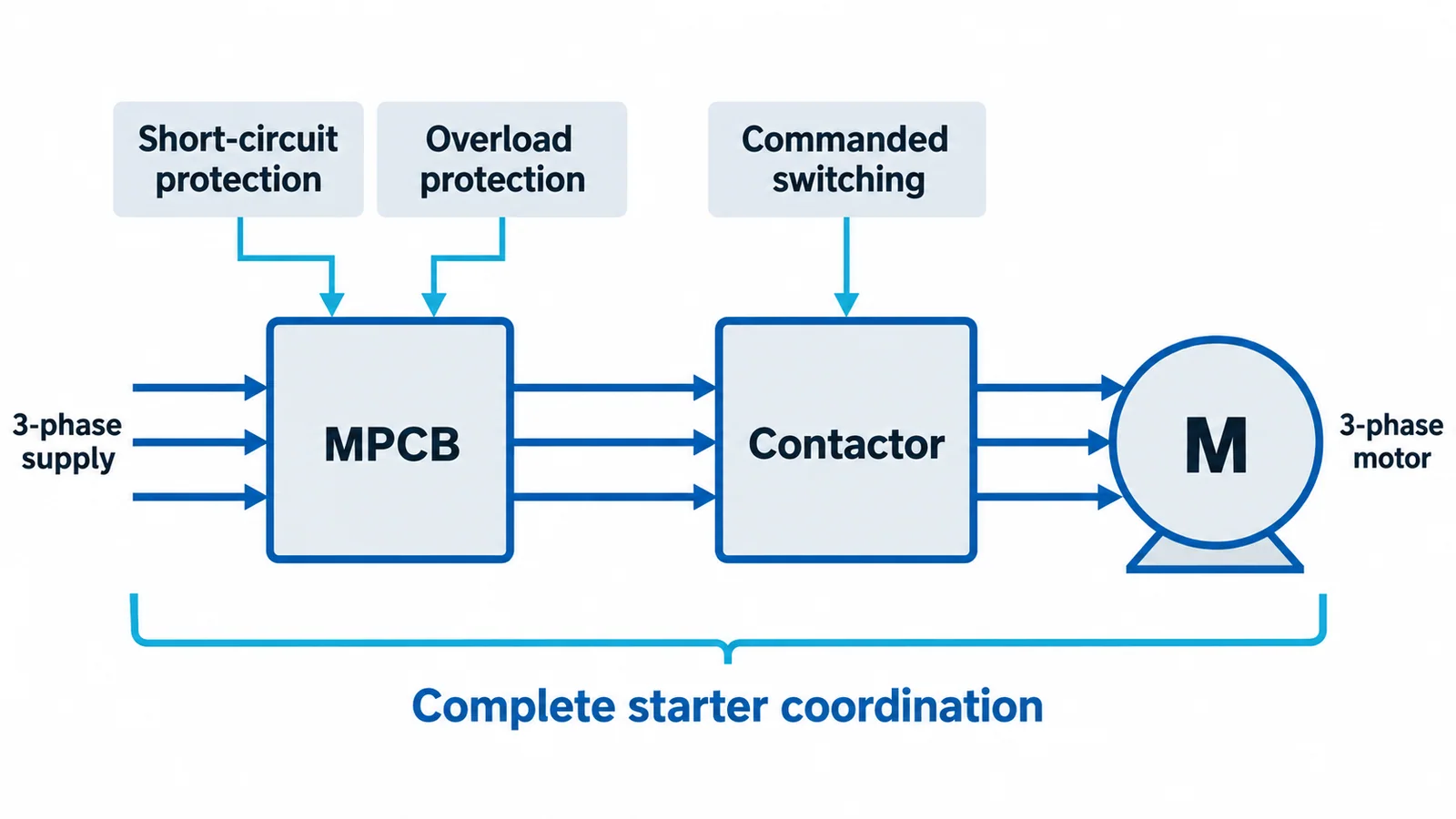
An MPCB is not automatically a complete motor starter. A contactor is still normally required for frequent or remote starting, and the installation may need separate isolation, ground-fault protection, undervoltage protection, or a branch-circuit protective device. The permissible combination depends on the jurisdiction, device markings, test evidence, and the complete assembly rating.
The four jobs in a motor circuit
Motor circuits are easier to design when each function is named separately:
| Function | Typical device | What it must handle |
|---|---|---|
| Isolation or disconnecting | Disconnect switch, suitable circuit breaker, or suitable MPCB | Safe separation under defined conditions and local rules |
| Short-circuit protection | Fuse, circuit breaker, or qualified MPCB function | High fault current within interrupting/SCCR limits |
| Overload and phase-failure protection | Overload relay or MPCB overload release | Sustained overcurrent related to motor heating, with starting tolerance |
| Operational switching | Contactor, starter, soft starter, VFD, or manual controller | Expected starts per hour, utilization category, duty, and control method |
One product may perform several jobs, but only within its evaluated ratings. “It trips on current” does not prove that it is suitable for isolation, branch-circuit protection, short-circuit interruption, or frequent motor switching.
How an MPCB responds to current
Overload region
An overload is higher-than-intended current in an otherwise intact circuit. Motors can tolerate a short starting current but not indefinite overcurrent. The MPCB’s adjustable overload element is set with reference to the motor nameplate current, service conditions, duty, starting time, and applicable rules. Thermal or electronic sensing models the motor’s heating behavior more closely than a general fixed-curve breaker might.
Phase loss or severe current imbalance can overheat a three-phase motor even when the remaining phase currents do not look extreme. Many MPCBs are designed to respond to phase failure, but the exact characteristic must be verified from the product documentation and applicable standard.
Short-circuit region
A short circuit produces a much faster and larger current rise. The magnetic or instantaneous element operates rapidly, subject to its pickup tolerance and the available fault current. The device must have adequate interrupting capacity for the installation, or be applied as part of an evaluated coordinated combination with an upstream short-circuit protective device.
The overload dial is not an adjustable short-circuit rating. Similarly, a high interrupting rating does not prove that the motor, contactor, conductors, and enclosure will remain serviceable after a fault.
The standards boundary matters
IEC 60947-4-1:2023, including its 2026 corrigendum, covers electromechanical contactors and starters, including motor-protective switching devices, for circuits up to 1,000 V AC or 1,500 V DC within its scope. It addresses overload-protection methods and coordination of an MPSD with a short-circuit protective device.
IEC 60947-2:2024 covers low-voltage circuit breakers intended for operation by instructed or skilled persons, generally up to 1,000 V AC or 1,500 V DC. A device may have claims under one or more parts of the IEC 60947 family; the actual marking and certificate determine the functions established for that model.
In North America, product categories and installation-code roles use different terminology. UL’s combination motor-controller guidance distinguishes combinations such as inverse-time circuit breaker plus controller and overload relay, and Type E or Type F self-protected arrangements. A device called an MPCB in an IEC catalog should not be assumed to satisfy a North American branch-circuit function without the applicable listing and markings.
Seven inputs for selecting an MPCB
1. Motor nameplate and application current
Record rated voltage, frequency, full-load current, power, efficiency, power factor, connection, duty, service factor where applicable, insulation class, and any manufacturer-defined limits. Use the actual nameplate and design documentation rather than estimating current from kW alone.
2. Starting method and acceleration profile
Direct-on-line starting can produce several times rated current. High-inertia loads may take longer to accelerate. Star-delta, autotransformer, soft-starter, and VFD systems create different current profiles and protection boundaries. The MPCB must ride through normal starting but trip before the motor or conductor exceeds its thermal limit during a stalled or abnormal start.
3. Adjustment range and trip characteristic
The motor current should fall comfortably within the device’s adjustable range—not at an uncertain extreme. Confirm the overload class or time-current characteristic, ambient compensation, phase-loss response, reset behavior, and tolerance. Where a VFD feeds the motor, verify whether the protective device belongs on the line side, output side, or both according to the drive and motor design; do not place ordinary switching devices on a drive output without explicit suitability.
4. System voltage and utilization duty
Check operational voltage, insulation voltage, impulse withstand where relevant, frequency, poles, and utilization category. The contactor and MPCB must be suitable for the motor duty, including starts per hour, jogging, plugging, reversing, and inching if required.
5. Available short-circuit current
Calculate or obtain the maximum prospective fault current at the installation point. Verify the MPCB’s interrupting capacity and the complete panel or starter short-circuit current rating. If the rating depends on a specific upstream fuse, breaker, current limiter, bus spacing, conductor size, or contactor, preserve that exact evaluated combination.
6. Coordination with the contactor and upstream device
Short-circuit coordination addresses the condition of the starter after a fault. IEC coordination types and North American combination ratings are not interchangeable labels. Use the manufacturer’s tested coordination tables or certification data for the exact MPCB, contactor, overload function, voltage, fault level, and upstream protection.
7. Environment and enclosure
Ambient temperature, altitude, enclosure temperature rise, mounting orientation, grouping, vibration, dust, humidity, corrosive atmosphere, and hazardous-area classification can change selection. Terminal conductor class, material, size, preparation, and tightening method must also match the device instructions.
MPCB versus MCCB plus overload relay
| Question | MPCB approach | MCCB or fuse plus overload relay |
|---|---|---|
| Footprint | Often compact | More components and wiring |
| Motor overload adjustment | Usually integrated | Provided by a separate overload relay |
| Remote switching | Still needs a contactor in most automatic starters | Also normally needs a contactor |
| High fault levels | Depends on device and tested combination | Broad choices, including current-limiting fuses or higher-rated breakers |
| Protection flexibility | Good for standard motor feeders | Can support more specialized relay functions and larger motors |
| Replacement and coordination | Combination-specific | Also combination-specific; components cannot be mixed casually |
Choose an MPCB when its current range, trip curve, short-circuit performance, starter coordination, certification, and control architecture fit the motor. Choose a separate breaker or fuse plus overload relay when fault duty, specialized protection, very large motor current, process requirements, or standard panel architecture make the modular approach more suitable.
Example selection logic
Assume a 400 V three-phase motor has a nameplate current of 32 A and starts direct-on-line. A sound preliminary process is:
- Select an MPCB whose adjustable overload range contains 32 A with reasonable margin.
- Set the overload function according to the motor nameplate, application, applicable standard, and device instructions—not simply to the top of the range.
- Plot or compare the motor starting current and acceleration time with the MPCB time-current characteristic, including tolerance and hot/cold state.
- Determine maximum and minimum fault current at the starter.
- Verify interrupting capacity and the panel SCCR at the system voltage.
- Select a contactor for the utilization category and duty.
- Verify the exact tested MPCB-contactor coordination at the required fault level.
- Check cable protection, voltage drop, terminal suitability, enclosure temperature, and isolation requirements.
The numbers above are deliberately incomplete. Without the available fault current, starting trace, duty, conductor data, and device-specific coordination evidence, a final catalog number or setting would be unjustified.
Common design errors
- Selecting only from motor kW and ignoring the nameplate current.
- Setting the overload dial high to stop nuisance trips instead of investigating acceleration time, mechanical load, voltage, imbalance, duty, or device mismatch.
- Confusing interrupting capacity with the starter assembly’s SCCR.
- Combining an MPCB and contactor that have not been evaluated together for the required coordination level.
- Assuming phase-loss protection covers every current-unbalance or thermal condition.
- Ignoring ambient heating and grouping inside a motor-control center.
- Using an ordinary MPCB as a disconnecting means without verifying suitability for isolation and local rules.
- Treating an IEC motor-protective device as automatically equivalent to a North American self-protected combination controller.
Commissioning and maintenance checks
- Verify nameplates, certification marks, voltage, frequency, current range, and coordination table.
- Confirm the short-circuit study and panel rating remain current after system changes.
- Record overload setting and the engineering basis.
- Perform de-energized mechanical checks and manufacturer-required tests.
- Verify phase sequence, control logic, interlocks, emergency stop, and contactor dropout behavior.
- Measure operating current and imbalance under representative load.
- Investigate discoloration, abnormal heating, loose connections, repeated trips, or contactor damage; do not simply reset and re-energize.
Electrical work must follow the employer’s energy-control program and applicable law. In the United States, OSHA 1910.333 generally requires exposed live parts to be de-energized before work unless specific exceptions apply, with qualified-person and work-practice requirements for energized work.
Bottom line
An MPCB is selected as part of a motor feeder, not in isolation. Start with the motor current and starting profile, then prove the overload characteristic, short-circuit capacity, contactor coordination, assembly SCCR, conductor protection, environmental suitability, and jurisdictional role. If any link in that chain is missing, the design is not complete.