
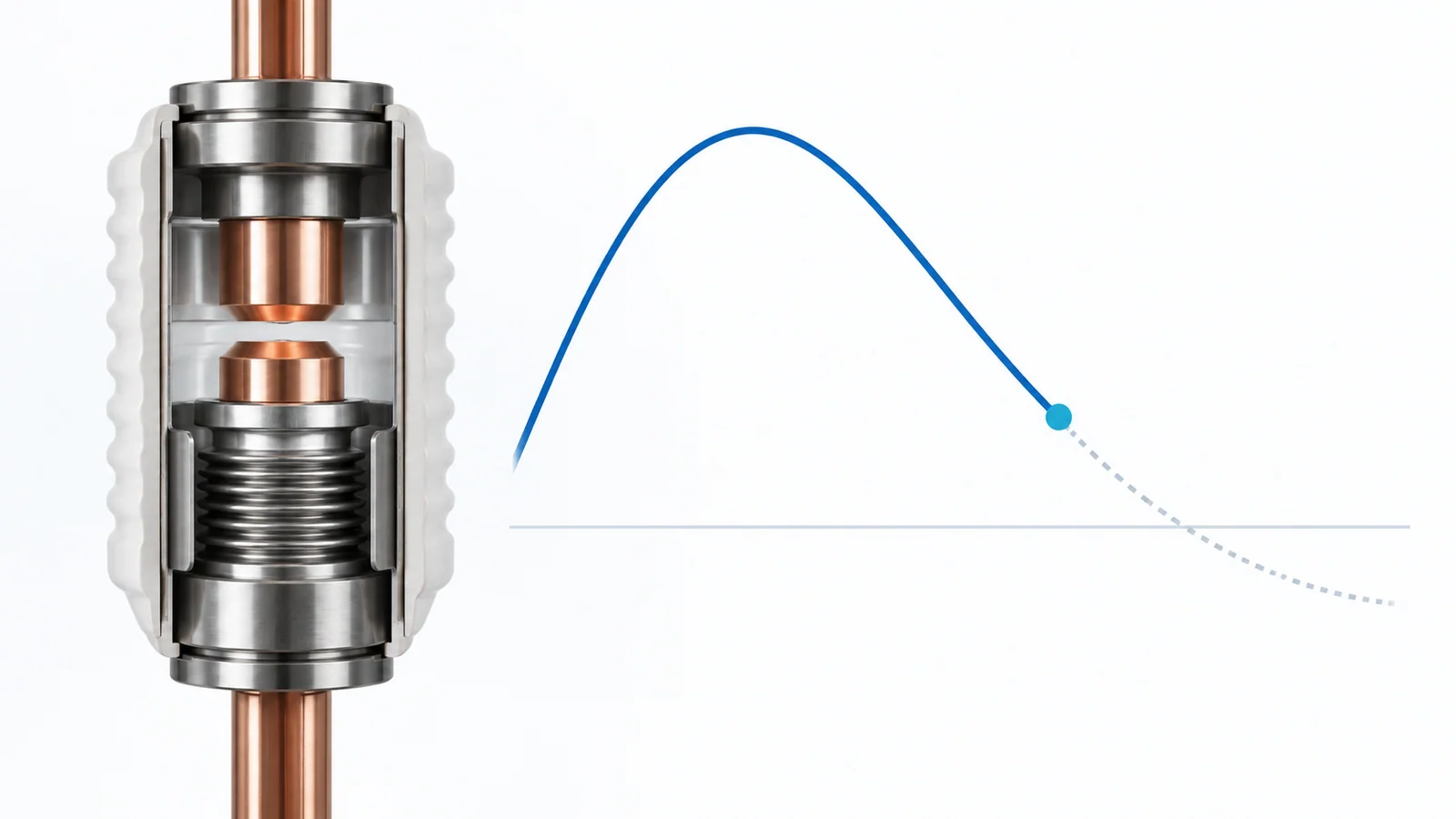
Current chopping is the premature extinction of alternating current before its natural current zero. In a vacuum circuit breaker, a small inductive current may become unable to sustain the vacuum arc and collapse abruptly while several amperes still flow. The remaining magnetic energy then moves into the circuit capacitance, creating a fast switching overvoltage.
That is why early arc extinction is not automatically beneficial. It may reduce arcing time, but the combination of chopping current, load inductance, effective capacitance, cable behavior and breaker dielectric recovery can stress motor, transformer or reactor insulation. The chopping current is also not the breaker’s rated breaking current; the two describe entirely different quantities.
What current chopping means
In an ideal AC interruption, the contacts separate, an arc carries current for part of a cycle, and the arc extinguishes near a natural current zero. At 50 Hz, a current zero occurs every 10 ms; at 60 Hz, every 8.33 ms.
With current chopping, the arc becomes unstable and extinguishes before that zero. If the instantaneous current falls from 5 A to zero, the chopping current for that event is 5 A:
5 A → 0 A before natural current zero
Vacuum interrupters deserve particular attention because they can interrupt small currents effectively, but chopping is not a simple measure of “how strong” a breaker is. It depends on the interrupter design, contact material, arc state, opening instant and external circuit. IEEE-published experimental work has shown that changing the vacuum contact material changes chopping and post-arc behavior.
| Term | What it describes | What it does not describe |
|---|---|---|
| Chopping current, Ic | Instantaneous current at premature arc extinction | Rated normal current or maximum fault-breaking current |
| Breaking current | Current the switching device is required and rated to interrupt under a stated duty | The residual few amperes at a particular chop |
| Transient recovery voltage, TRV | Voltage appearing across the opening switching device after interruption | The load-terminal voltage alone |
| Reignition | Dielectric breakdown of the recovering contact gap after interruption | A necessary part of every chopping event |
For a broader map of device functions, see switching devices in medium-voltage switchgear.
Why a few amperes can produce kilovolts
The key is stored energy, not the small numerical value of the current by itself.
An inductive load carrying chopping current Ic stores magnetic energy approximately equal to:
EL = 1/2 × L × Ic²
where L is the effective inductance seen in the transient. When the current is forced to zero, that energy cannot disappear instantaneously. In a simple lossless model, it transfers into the effective capacitance C of the cable, switchgear, winding and connected equipment:
EC = 1/2 × C × Vch²
Equating the two energies gives a first-order chopping-voltage component:
Vch ≈ Ic × √(L/C) = Ic × Z0
where Z0 = √(L/C) is the equivalent surge or characteristic impedance of the simplified circuit.
This relationship explains the risk:
- higher chopping current increases the idealized voltage component linearly;
- higher inductance stores more energy;
- lower effective capacitance produces a larger voltage rise for the same energy;
- the same current chop can therefore produce very different results in two installations.
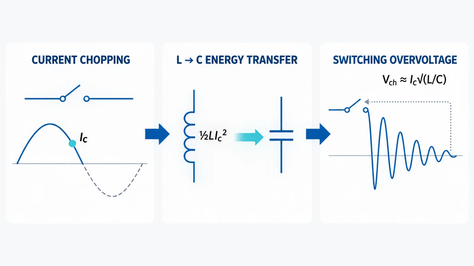
The equation is an educational model, not a terminal-voltage guarantee. Real systems also contain losses, initial power-frequency voltage, three-phase coupling, cable travel and reflections, winding resonances, nonlinear surge protection and a time-varying contact gap.
A 1 A versus 5 A sensitivity example
Assume an illustrative equivalent characteristic impedance of 3,000 Ω. Applying Vch ≈ Ic × Z0 gives:
| Assumed chopping current | Calculated chopping-voltage component | Relative magnetic energy for the same L |
|---|---|---|
| 1 A | 3 kV | 1× |
| 5 A | 15 kV | 25× |
The voltage component is five times larger, while the magnetic energy is 25 times larger because energy varies with Ic².
These values must not be read as universal contactor and breaker ratings. The often-repeated comparison of about 1 A for a vacuum contactor and about 5 A for a vacuum circuit breaker comes from particular designs and application examples. Modern interrupters, contact materials and products differ, and a procurement specification should use declared or tested switching data for the offered device.
The calculated 3 kV and 15 kV values also are not complete per-unit overvoltages. Converting them into an insulation stress requires the system phase voltage at the switching instant, grounding, damping, capacitance distribution, wave reflection, protective-device behavior and the voltage actually appearing at the vulnerable winding terminals.
Which loads are most exposed
Current chopping is most relevant when the interrupted current is inductive and relatively small.
Motors
Medium-voltage motors can be exposed during opening at light load, no load or near the end of a starting or operating sequence. The cable and motor winding form a high-frequency network, so both peak voltage and front steepness matter. A surge arrester may limit peak magnitude yet not, by itself, resolve every steep-front or internal winding-distribution concern.
Transformers
An unloaded or lightly loaded transformer draws magnetizing current. Premature interruption can excite oscillations among source, cable and transformer capacitances and the transformer’s frequency-dependent winding impedance. A transformer cannot be represented reliably by one lumped capacitance when a detailed insulation-coordination decision is required.
Shunt reactors
Reactor current interruption is a recognized severe switching duty because the circuit is deliberately inductive. IEC 62271-110:2023 covers AC switching devices above 1 kV used for high-voltage motor-current and shunt-reactor-current switching. IEEE C37.015-2017 provides application guidance for shunt-reactor switching, including overvoltage generation and limitation.
The load name alone does not determine risk. A long cable adds capacitance and changes wave travel; it may reduce one component of the local voltage rise while creating reflection or resonance behavior elsewhere. Grounding and three-phase coupling can also move the highest stress away from the first pole to clear.
Current chopping is only the first event
A simple chopping calculation assumes the arc extinguishes once and the gap continues to withstand the recovery voltage. That is not always what happens.
- Current chopping: the arc extinguishes at Ic before natural zero.
- Voltage recovery: the load-side LC circuit oscillates while voltage builds across the opening contacts.
- Reignition: if the recovering dielectric strength is lower than the imposed voltage, the gap breaks down and current flows again.
- High-frequency interruption: the reignited high-frequency current may reach another zero and be interrupted.
- Multiple reignition: repeated breakdown and interruption can produce a sequence of steep voltage steps and three-phase coupling effects.
This distinction matters because the most damaging case may be controlled less by the original chopping current than by the repeated interaction between circuit oscillation and dielectric recovery. Field-test research published in IEEE Transactions on Power Delivery found that multiple reignitions, breaker differences and application conditions were important in severe 40.5 kV shunt-reactor switching overvoltages.
CIGRE’s material on vacuum current interruption likewise treats post-arc particles and dielectric recovery as central to successful interruption. Chopping current alone is therefore not a complete equipment-selection metric.
Vacuum contactor versus vacuum circuit breaker
Both devices may use vacuum interrupters, but they are assigned different system duties.
- A vacuum circuit breaker is selected for stated making and breaking duties, including fault interruption, under standards such as IEC 62271-100:2021+A1:2024.
- A high-voltage contactor or contactor-based motor starter is intended for frequent operational switching within the scope and ratings of IEC 62271-106:2021; higher fault current is commonly handled by a coordinated fuse or another protective device.
Different contact metallurgy and interrupter optimization can give a contactor a lower chopping tendency than a breaker used in a motor application. That is a possible design characteristic, not a rule established merely by the words “contactor” and “circuit breaker.” Request the offered device’s inductive-load switching evidence, chopping behavior, permitted operating duty and complete protection arrangement.
The selection decision should still start with fault-clearing responsibility and operating frequency. OHELE’s medium-voltage circuit breaker versus contactor guide covers that broader decision.
What controls the actual overvoltage
| Input | Why it matters |
|---|---|
| Chopping-current distribution | Establishes the residual magnetic energy at interruption; one nominal value may not represent statistical behavior |
| Load inductance and high-frequency model | Controls stored energy and oscillation; motor, transformer and reactor models are not interchangeable |
| Effective capacitance | Includes cable, bus, switchgear, winding and stray capacitances at the relevant frequency |
| Cable length and surge impedance | Change wave travel, reflection, terminal voltage and oscillation frequency |
| System grounding and phase coupling | Affect first-pole-to-clear conditions and phase-to-ground or phase-to-phase stress |
| Breaker dielectric recovery | Determines whether the gap withstands the recovery voltage or reignites |
| High-frequency current-quenching behavior | Influences repeated interruption after reignition |
| Surge-protection type and location | Determines the protected point, residual voltage, front control and absorbed energy |
| Opening-time scatter and point on wave | Change arcing time and the initial conditions for each operation |
CIGRE describes shunt-reactor interruption as a combined interaction among the switching device, inductance, effective capacitance and grounding. That is the correct application mindset for motors and transformers too: the breaker cannot be assessed independently of the connected circuit.
How engineers evaluate and limit the risk
There is no universal surge-protection package for every vacuum-switched inductive load. A defensible workflow is:
- Define the operating cases. Include normal opening, light-load or no-load operation, starting or stopping states, abnormal trips, bus configurations and credible cable arrangements.
- Obtain device-specific data. Request inductive-load switching test evidence, chopping characteristics, reignition behavior or model parameters appropriate to the offered interrupter—not only fault-breaking current.
- Build a frequency-appropriate circuit model. Represent source, grounding, cables, switchgear, load and protective devices. Detailed studies commonly use electromagnetic-transients software and statistical switching cases.
- Evaluate peak and steepness at the vulnerable terminals. The breaker-side voltage alone may not reveal motor or transformer winding stress.
- Compare mitigation options in the same model. Options can include a lower-chopping switching device, surge arresters placed near the load, surge capacitors, RC snubbers or filters, and controlled switching where the application and equipment support it.
- Verify ratings and energy duties. Check arrester temporary overvoltage, residual voltage and energy; capacitor and resistor voltage, energy and thermal duty; clearances; insulation coordination; and the switching device’s tested application.
- Validate commissioning and monitoring plans. Where risk justifies it, use suitable transient measurement methods and qualified specialists; ordinary power-quality instruments may not capture very fast events.
IEEE literature identifies surge capacitors and RC snubbers as established very-fast-transient mitigation families, but their component values and location must come from the actual network model. Adding capacitance without analysis can move a resonance or increase another switching duty.
Specification questions to ask
Before approving a vacuum switching application for an inductive load, ask:
- What exact load is being switched, at what operating current and how often?
- Which standard and special switching duty apply to the complete device or assembly?
- What chopping-current data or statistical model is available for the offered interrupter?
- What are the cable length, surge impedance, grounding and relevant capacitances?
- Does the load require a frequency-dependent motor, transformer or reactor model?
- What dielectric-recovery and reignition assumptions are used?
- Are phase-to-ground, phase-to-phase and terminal front-steepness stresses all checked?
- Where will surge protection be installed, and what peak, energy and frequency content must it control?
- Have component tolerances, operating-time scatter and credible system configurations been included?
- What field evidence or test report will confirm the final arrangement?
Bottom line
Current chopping is premature current interruption, not the breaker breaking-current rating. In a small inductive-current circuit, the magnetic energy remaining at the chopping instant transfers into a relatively small capacitance and can create a steep switching overvoltage. The useful first-order relationship is Vch ≈ Ic√(L/C), but it only explains sensitivity; it does not predict the final terminal stress.
The real application problem includes the breaker, load, cable, grounding, protective devices and the possibility of reignition. Use device-specific data and a switching-transient study when insulation risk is material—especially for medium-voltage motors, lightly loaded transformers and shunt reactors.
Sources
- IEC 62271-110:2023 — Inductive load switching
- IEC 62271-100:2021+A1:2024 — Alternating-current circuit breakers
- IEC 62271-106:2021 — AC contactors, contactor-based controllers and motor starters
- IEEE C37.015-2017 — Guide for the Application of Shunt Reactor Switching
- CIGRE WBN025 — Shunt reactor switching: theory and practice
- CIGRE WBN053 — Fundamentals of Current Interruption in Vacuum Circuit Breakers
- IEEE Transactions on Power Delivery — Overvoltages from 40.5 kV VCB shunt-reactor switching