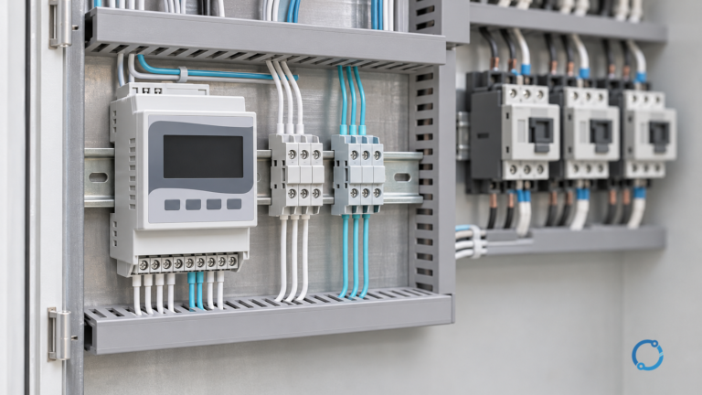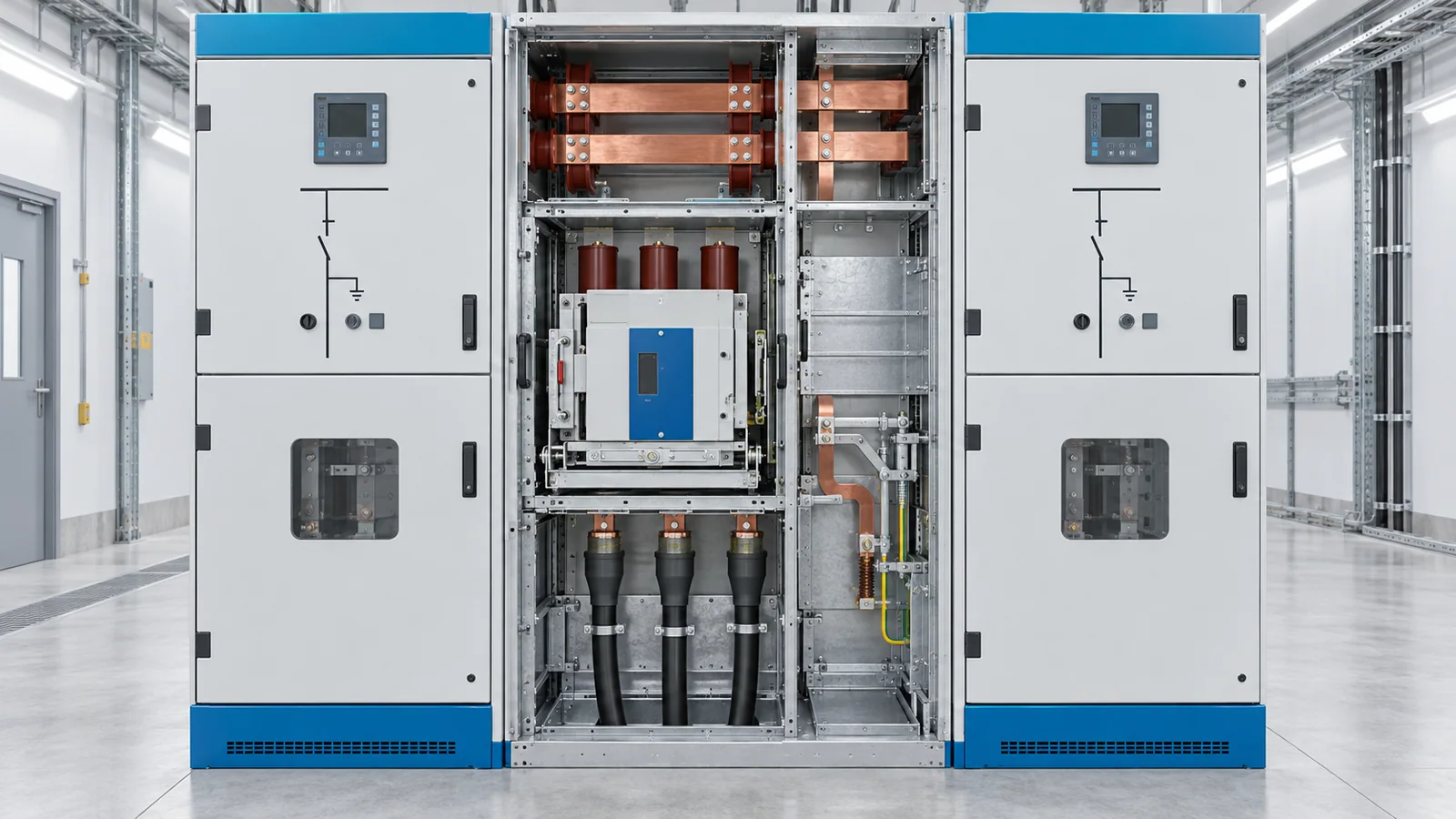
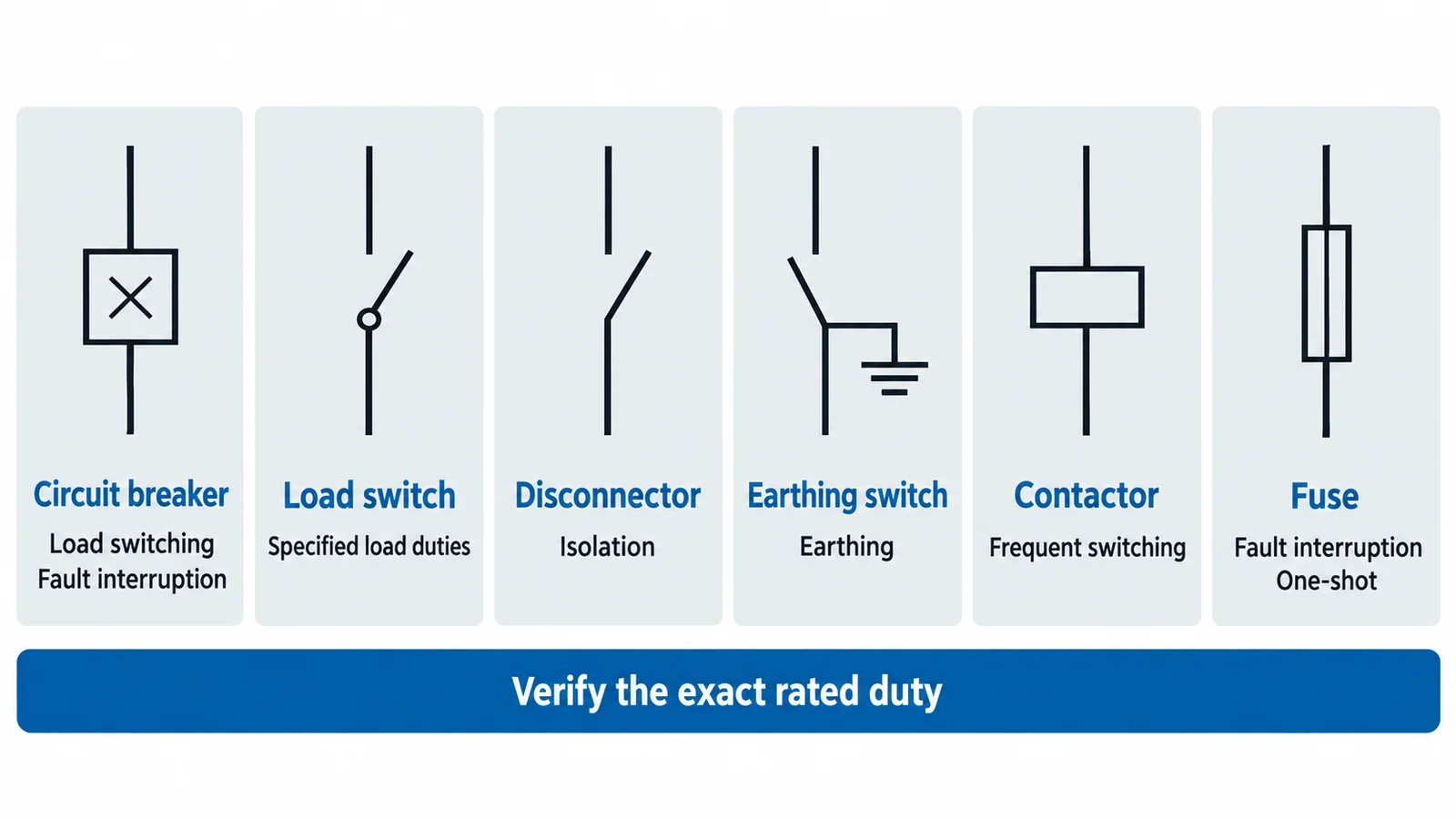
Medium-voltage switchgear uses different devices for different electrical duties. A circuit breaker can interrupt specified fault currents; a load switch interrupts specified normal or limited abnormal currents; a disconnector establishes isolation; an earthing switch connects an isolated circuit to earth; a contactor performs frequent operational switching; and a fuse interrupts by melting under overcurrent.
Those functions can be packaged together, but they do not become interchangeable. Safe specification and operation depend on the exact rated duties, interlocks, switchgear classification, system studies, and locally approved switching procedures.
Start with the duty, not the device name
Before choosing a switching device, define what current and voltage it must make, carry, and break:
- normal continuous current;
- transformer, motor, reactor, or capacitor load current;
- cable- or line-charging current;
- magnetizing or inrush current;
- load-transfer or loop current;
- prospective short-circuit current;
- earth-fault current;
- transient recovery voltage after interruption;
- short-time and peak withstand current;
- switching frequency and mechanical endurance.
A device described generically as a “switch” may have a specific load-breaking capability but no general short-circuit breaking rating. A disconnector may carry normal and short-time current when closed yet be unsuitable for opening load current. The nameplate and applicable product standard, not the mimic symbol alone, establish capability.
Device-by-device comparison
| Device | Normal load switching | Fault-current interruption | Isolation function | Typical role |
|---|---|---|---|---|
| Circuit breaker | Yes, within ratings | Yes, within rated making and breaking duties | Only if designed and arranged to provide required isolation | Feeder, transformer, bus, generator, or motor protection |
| Load switch / switch-disconnector | Yes, for specified duties | Usually not general fault interruption; may make onto a fault within rating | A switch-disconnector also provides a disconnecting function | Ring-main units, transformer feeders, sectionalizing |
| Disconnector / isolator | Not the primary purpose; only specified limited currents | No general fault-breaking duty | Yes | Visible or assured isolation after current is interrupted elsewhere |
| Earthing switch | Not for carrying normal load | May have a short-circuit making class; not a normal fault interrupter | Applies earth to an isolated section | Personnel protection and control of induced or trapped voltage |
| Contactor | Yes, especially frequent operations | Requires coordinated short-circuit protection | Normally no | Motor feeders, capacitor or reactor switching, process loads |
| Fuse | Not a reusable operational switch | Yes, within its rated interrupting capability | No by itself | Transformer or motor fault protection, often combined with a switch |
This table is functional, not a universal rating statement. The exact capability of a product depends on voltage, current, duty, class, test standard, and assembly.
Circuit breakers
An MV circuit breaker opens and closes a circuit under normal conditions and interrupts specified short-circuit currents. Vacuum interruption is common at medium voltage; other technologies exist depending on voltage class and installed base.
IEC 62271-100:2021, consolidated with later amendment content on the IEC page, applies to three-phase AC circuit breakers above 1,000 V. Ratings extend beyond a single kA number: rated voltage, normal current, short-circuit breaking current, short-circuit making current, operating sequence, short-time withstand, first-pole-to-clear factor, transient recovery voltage, capacitive switching class, and mechanical/electrical endurance may all matter.
The protection relay decides when to trip; the breaker provides the interruption. A breaker with adequate interrupting capacity can still be misapplied if the relay scheme, CT performance, DC trip supply, arc classification, cable charging duty, or transient recovery voltage is wrong.
Load switches and switch-disconnectors
A load switch is designed to make and break specified load currents and may have defined duties for cable charging, transformer magnetizing current, closed-loop current, or other applications. It is not automatically able to interrupt the full prospective short-circuit current.
IEC 62271-103:2021 covers AC switches and switch-disconnectors above 1 kV up to and including 52 kV for specified making and breaking duties. The switch may be paired with fuses so the switch handles operational current while the fuse clears faults within the coordinated combination’s limits.
A switch-disconnector combines a switching function and a disconnecting function. That wording still does not establish every duty; the product rating and assembly design remain decisive.
Disconnectors
A disconnector provides an isolating distance or equivalent assured isolation in the open position. It is generally operated only after another device has interrupted load or fault current. Some disconnectors have limited current-switching ratings, such as bus-transfer or charging duties, but those named capabilities must not be generalized into full load-breaking ability.
IEC 62271-102:2018, with its 2022 amendment, covers AC disconnectors and earthing switches above 1,000 V. It addresses matters including isolating distance, position indication, mechanical interlocking, current-switching capabilities, and earthing-switch making classes.
In metal-enclosed switchgear, the isolating function may be provided by a withdrawable breaker position, a three-position switch, or another tested arrangement. A viewing window is not necessarily the only means of assured isolation; follow the assembly’s certified design and operating instructions.
Earthing switches
An earthing switch intentionally connects de-energized, isolated conductors to earth. Its purpose is to control hazardous voltage from accidental energization, induction, capacitance, or trapped charge as part of an approved safety process.
Some earthing switches have a rated short-circuit making capability so they can close onto an accidentally energized circuit without immediate mechanical failure. That is not permission to use them as fault interrupters or to substitute them for verification of de-energization. Interlocks commonly prevent closing an earthing switch onto an energized circuit and prevent energizing a circuit while earthed.
Portable protective grounds and fixed earthing switches also have different application rules. In U.S. electric-power work within its scope, OSHA 1910.269 requires lines and equipment to be treated as energized until de-energized under the specified procedure and addresses protective grounding to create an equipotential zone.
Contactors and motor-switching devices
MV contactors are suited to frequent operation, making them common for motors, capacitors, reactors, and other process loads. They typically rely on fuses or a circuit breaker for high-level short-circuit protection. Selection considers utilization duty, number of operations, inrush, starting time, stalled-motor current, switching transients, and the coordinated fuse or breaker.
A contactor’s high mechanical endurance does not imply a circuit-breaker-level fault-interrupting capability. Conversely, a circuit breaker capable of interrupting faults may not be the most economical device for very frequent process switching.
Fuses and switch-fuse combinations
An MV current-limiting fuse can interrupt high fault current rapidly and reduce let-through energy. It is a single-operation device and usually needs a switch or contactor for normal operation. Transformer protection often uses a switch-fuse combination in which striker operation opens the phases through a coordinated mechanism.
Verify minimum breaking current, maximum interrupting current, time-current curve, transformer inrush or motor-starting ride-through, striker energy, transfer current, backup protection, phase-loss consequences, and replacement practice. Replacing only one fuse after a multi-phase event can be inappropriate unless the applicable instructions and investigation support it.
The switchgear assembly changes the decision
IEC 62271-200:2021, with amendment information shown on the IEC page, applies to prefabricated AC metal-enclosed switchgear above 1 kV through 52 kV. It addresses the assembly, not just its devices, including service-continuity classification, partition class, interlocks, earthing circuits, and internal-arc classification where specified.
Important assembly questions include:
- Is the equipment air-insulated, gas-insulated, solid-insulated, or hybrid?
- Are devices fixed, removable, or withdrawable?
- Which compartments can remain energized during access?
- What loss-of-service-continuity category and partition class apply?
- Is internal-arc classification required, and from which accessible sides?
- How are cable testing, phase checking, voltage detection, and earthing performed?
- What interlocks prevent an invalid switching state?
- What environmental conditions, pressure systems, and maintenance needs apply?
An internal-arc classification is not a guarantee of operator safety under every event. Installation, room geometry, pressure relief, accessibility, fault duration, and adherence to operating procedures remain relevant.
A conceptual switching-state sequence
For an outgoing feeder, the safe state logic is generally:
- Interrupt load current with a device rated for that duty.
- Establish isolation using the designed disconnecting means.
- Verify the absence of voltage with the approved method.
- Apply earths according to the system and safe-work procedure.
- Control access and work boundaries.
Returning to service reverses the intent: clear the work zone, remove earths under authorization, restore the disconnecting state, then close the load- or fault-interrupting device as the approved operating procedure requires.
This is a functional model, not a field switching order. Actual sequences depend on the one-line diagram, backfeeds, interlocks, trapped energy, induced voltage, station rules, remote control, permits, and jurisdiction. Only authorized qualified personnel may perform switching.
Selection checklist
- System maximum voltage, frequency, grounding, and insulation level
- Maximum and minimum fault current and required clearing time
- Normal current and load type
- Making, breaking, charging, inrush, and transfer duties
- Short-time and peak withstand ratings
- Transient recovery voltage and special switching duties
- Mechanical and electrical endurance
- Isolation and earthing method
- Protection, control power, interlocks, and remote-operation philosophy
- Switchgear LSC, partition, internal-arc, and environmental classifications
- Cable interface, testing access, surge protection, and phase spacing
- Applicable standards editions, local adoption, utility rules, and competent-person review
Bottom line
Medium-voltage switchgear is safe and selective only when each device is assigned the duty it was designed and tested to perform. Use circuit breakers for specified fault interruption, load switches for defined load duties, disconnectors for isolation, earthing switches for grounding an isolated section, contactors for frequent operation, and fuses for one-shot overcurrent interruption. Then verify how those devices interact inside the complete assembly.
For a specific switching duty, compare medium-voltage circuit breakers and contactors. Isolation and earthing require a separate decision, covered in disconnector and earthing-switch selection.
For the next stage of a switchgear review, compare SF6 and vacuum interruption, check the required breaker operating sequence, and use the pre-energization evidence gates before release.
References
- IEC 62271-100:2021 — AC circuit breakers
- IEC 62271-102:2018 — Disconnectors and earthing switches
- IEC 62271-103:2021 — AC switches above 1 kV through 52 kV
- IEC 62271-200:2021 — AC metal-enclosed switchgear above 1 kV through 52 kV
- OSHA 1910.269 — Electric power generation, transmission, and distribution
For related equipment and application checks, see Fixed vs. Withdrawable MV Switchgear: Maintenance, Floor Space and Interlocking.