
Medium-voltage (MV) switchgear is ready for initial energization when the installed assembly, its protection and control interfaces, and its restored operating configuration have traceable acceptance evidence. A passing insulation-resistance measurement, a factory certificate or one successful breaker operation cannot establish that complete result alone.
Use a controlled sequence: reconcile design and delivered equipment, verify the installation, execute the approved electrical and functional test matrix, close material exceptions, and confirm restoration before an authorized energization release. This article explains those gates, not a switching order or a list of universal test values.
Set the equipment and work boundary
The scope here is prefabricated alternating-current (AC) metal-enclosed switchgear assemblies in the MV range. The International Electrotechnical Commission (IEC) scope for IEC 62271-200:2021+AMD1:2024 covers AC assemblies above 1 kV through 52 kV, at service frequencies up to 60 Hz, for indoor and outdoor installations. Other equipment families and higher voltages need their applicable standards and procedures.
Determine the contractual acceptance documents, applicable editions and site rules. The official ANSI/NETA ATS-2025 scope addresses field tests and inspections used to assess suitability for initial energization. Its public page is not the full test specification, and naming it does not make every test or criterion applicable to every assembly.
Only competent, authorized personnel should perform commissioning. Identify every source, backfeed, induced-voltage exposure and stored-energy mechanism. Test instruments themselves may apply hazardous voltage. Temporary grounds, test connections, isolation and restoration must be controlled by approved procedures.
For applicable U.S. general-industry work, OSHA 1910.333 sets de-energization, lockout/tagout and qualified-person verification boundaries. Utility and other sites must determine the provisions that actually govern their work. A breaker-open indication is not verified absence of voltage.
Keep four kinds of evidence separate
| Evidence | Question it answers | What it cannot establish by itself |
|---|---|---|
| Design/type-test evidence | Is the specified equipment design supported for its declared duty? | Correct installation of the delivered site assembly |
| Routine/manufacturing records | Did the identified delivered equipment receive the applicable production checks? | Undamaged transport, assembly and site connections |
| Factory acceptance test (FAT) | Were agreed factory configuration and functional requirements demonstrated? | Every site cable, auxiliary supply, network or plant interface |
| Site inspection and acceptance tests | Does the actual installation meet its approved criteria and perform the specified functions? | An untested design change or a duty beyond the equipment evidence |
Trace records to the actual assembly, compartments and devices. A similar model’s report cannot silently cover a different configuration. Shipping splits, replacement components and site modifications need a documented reconciliation.
Confirm the system study against the installed ratings using the existing MV circuit-breaker rating crosswalk. Commissioning tests cannot increase an inadequate interrupting or withstand rating.
Use a release-gate matrix
The following is an engineering workflow, not a reproduced standards checklist. The project must supply the exact test methods, limits and sign-off authority.
| Gate | Evidence to retain | Hold condition |
|---|---|---|
| Design and equipment match | Approved drawings, duty study, equipment identity, configuration and test basis | Rating, revision or configuration discrepancy remains unexplained |
| Installation complete | Inspections of primary interfaces, bonding, supports, enclosure and required room arrangements | Damage, contamination, missing interface or unsupported modification |
| Electrical condition acceptable | Approved per-circuit/device test results with boundaries and instrument records | Failed result, invalid setup or missing applicable acceptance criterion |
| Required functions demonstrated | Interlock, protection, indication and command-path test records | A required function or failure-state response is not demonstrated |
| Restoration and release controlled | As-left configuration, exception disposition and authorized release | Temporary test state, removed protection or unresolved safety-critical item |
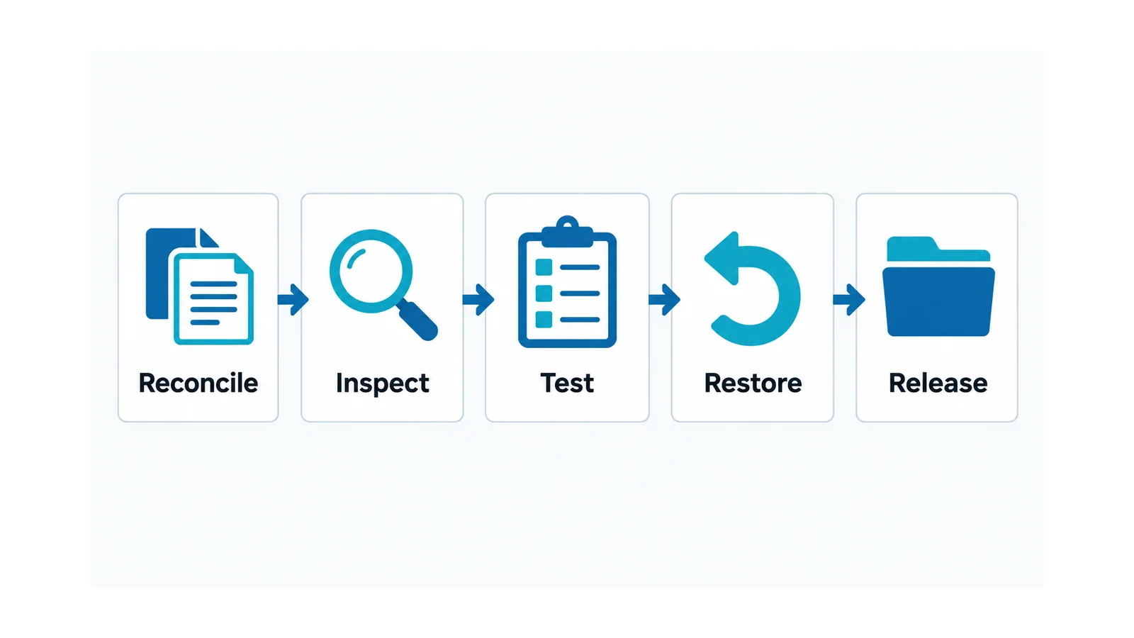
For each test, record purpose, equipment boundary, prerequisites, connection method, expected result, acceptance source and stop conditions before work starts. This prevents an impressive instrument reading from becoming evidence for the wrong circuit.
Inspect what transport and site work can change
Verify alignment and assembly of shipping sections, supports, accessible connection condition, enclosure integrity and the required protective-bonding path. Inspect insulation surfaces and compartments for contamination, moisture, foreign objects or damage. Follow the actual assembly instructions for interfaces and fastening; use no generic tightening value.
Check cable entries, termination clearances and connections against the accepted arrangement. Ensure that installed cables and accessories match their own verification evidence. Do not assume an assembly test automatically covers every connected cable.
Review the room and installation dependencies credited by the equipment design. Access, environmental controls and any required pressure-relief or exhaust arrangements must match the accepted equipment/application documentation. An internal-arc classification is conditional; it is not general permission for open-door energized work.
Record discrepancies with their exact location, consequence and owner. A cosmetic issue and an unexplained damaged insulating support do not deserve the same release decision.
Select electrical tests by boundary and purpose
Inspection, continuity/bonding checks, insulation assessment, resistance measurements and breaker mechanical/electrical checks may contribute different evidence, depending on the equipment and contract. They are not interchangeable demonstrations.
Before applying a test voltage, identify connected voltage transformers, surge arresters, electronic devices, cables and any other equipment that affects the test boundary. Determine what must be isolated, how that isolation is recorded and how it will be restored. Never choose a withstand voltage by multiplying the system’s nominal voltage without the applicable method and acceptance basis.
An insulation-resistance result is affected by the tested circuit, temperature, moisture and instrument/setup conditions. The insulation-resistance testing guide explains that interpretation task. A high reading alone does not prove every insulation interface has the required withstand capability.
Similarly, contact-resistance and breaker timing measurements require equipment-specific criteria and consistent test conditions. Do not borrow a universal micro-ohm limit, operating time or phase spread from an unrelated switchgear design.
Prove interfaces as complete functions
Confirm current-transformer (CT) and voltage-transformer (VT) identity, ratio, polarity, wiring, grounding arrangements and the scaling seen by the connected equipment. Keep dangerous secondary-circuit conditions under approved test procedures. The dedicated CT installation and testing workflow supplies the detailed CT boundary.
Reconcile the approved protection settings with the installed device, firmware/configuration and study revision. A successful secondary-injection test proves only the functions covered by its setup. It does not automatically prove primary polarity, trip wiring, breaker operation or the removal of every fault contribution.
For each required trip function, trace detection → logic → output → trip supply/path → breaker action and feedback. Use the substation trip-circuit verification checklist for that separate chain. Select controlled tests that demonstrate the agreed interfaces without accidentally tripping energized equipment elsewhere.
Check permitted and prohibited commands, local/remote authority, position indications and interlocks against the actual scheme. Where communications carry a required function, include the site-dependent path and defined unavailable-state behavior. A protocol connection alone is not functional acceptance.
Do not bypass an interlock to obtain a passing result. If a test configuration requires a specifically authorized temporary state, document its scope and restoration, and do not treat that temporary bypass as the normal operating arrangement.
Restore the as-left state before release
Use an approved restoration record for test leads, temporary connections, grounds, test switches, isolated interfaces and disabled or substituted functions. Some items must be removed, others restored or retained according to the energization procedure. A generic “remove all grounds” instruction is unsafe without the equipment and switching boundary.
Confirm the as-left protection configuration, auxiliary supplies, control authority, alarm state, drawings and physical closures. Require independent verification where the site’s procedure calls for it. Record who performed the restoration and who accepted the result.
An exception needs an explicit engineering disposition. A required function still awaiting proof is not closed because equipment delivery is late. Any accepted limitation must have a documented operating restriction, responsible authority and correction plan; safety-critical unknowns remain hold points.
The release file should connect equipment identity to the approved test matrix, actual results, resolved discrepancies and final configuration. Initial energization then proceeds only under the authorized site plan. Record subsequent observations through that plan, without opening energized equipment simply to finish an incomplete inspection.