
A substation battery charger must support the ongoing direct-current (DC) load while returning the charge removed from the battery within the accepted recovery period. Calculate those two demands separately, then check output voltage, battery charge acceptance, ambient derating and required operating states. Battery ampere-hours divided by a recharge time is only part of the current budget.
This method concerns conventional stationary battery-backed control and protection supplies, including nominal 110 V DC systems. It produces a preliminary charger requirement, not a complete battery-autonomy design or a prescription for the number of cells. Nominal system voltage is not the charger’s required float or recharge setpoint.
Define the supply and load boundary
Start with the auxiliary DC diagram and load schedule. Identify what the proposed charger supplies in normal service, after an outage and during permitted maintenance. Include protection relays, control electronics, communications, annunciation and other continuous loads actually connected to that system.
The distribution-substation overview explains the wider equipment relationships. For sizing, the relevant boundary is the DC source-to-load path, including any converter losses or additional circuits inside it.
Record these inputs before choosing a current rating:
| Input | Why it changes the result |
|---|---|
| Battery chemistry, cell count and charging instructions | Establishes permitted voltage, recharge behavior and charge-current limits |
| Continuous load during recovery | Uses charger capacity that is unavailable for battery recharge |
| Battery duty during the specified outage | Determines the Ah removed, including the timing of intermittent loads |
| Recovery target and permitted time | Sets the recharge-current budget and required recovery demonstration |
| Lowest alternating-current (AC) input and highest relevant ambient condition | May reduce the available charger output |
| Normal, degraded and maintenance configurations | Establishes what each available charger must support |
| Connected equipment voltage envelope | Limits float/recharge setpoints and distribution drop |
Keep instantaneous demand, energy duty and equipment voltage as different quantities. A trip coil may draw appreciable current briefly while contributing little Ah. A small relay load can remove substantial charge over a long outage.
Calculate withdrawn charge from the duty
For a piecewise constant battery-current schedule:
C_removed = Σ(I_j × Δt_j)
Here I_j is battery current in amperes and Δt_j is the interval in hours. Include simultaneous loads in the current for their shared interval. If an intermittent load is listed separately, ensure it has not already been included in the base current.
This bookkeeping calculates charge withdrawn. Battery sizing still needs the appropriate discharge-performance data, end voltage, temperature and aging/design criteria. A nameplate Ah rating at one discharge rate does not automatically establish the battery’s capability for the required station duty.
Do not substitute the entire nameplate capacity for charge removed unless the accepted design deliberately requires recovery from that discharge basis. Conversely, using only the usual outage history is inadequate when the specified duty is longer or more demanding.
Build a two-part charger-current budget
The U.S. Bureau of Reclamation’s FIST 3-6, April 2020, printed page 78 presents a charger-sizing relationship with continuous load plus a charge-return allowance. In clearer notation:
I_budget = I_cont + k × C_removed / T_recharge
| Symbol | Meaning | Unit |
|---|---|---|
| I_budget | Preliminary charger output-current requirement | A |
| I_cont | Continuous demand supported during recharge | A |
| C_removed | Calculated charge removed in the specified battery duty | Ah |
| T_recharge | Accepted recovery time for the stated target | h |
| k | Charge-return factor on the selected chemistry/method basis | Dimensionless |
FIST uses 1.1 for lead-acid in that relationship and describes the time basis as recovery to approximately 95% capacity. These are contextual Reclamation guidance, not universal settings for every stationary battery. Its recharge target should not be silently rewritten as full recovery in exactly the same time.
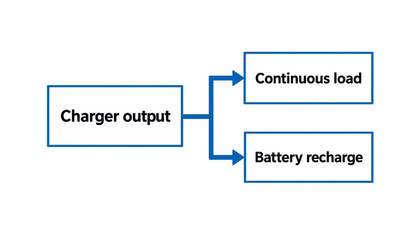
The dimensional check is straightforward: Ah/h = A. However, the expression does not prove that a battery can accept a constant recharge current throughout recovery. Charging behavior near the voltage limit, current limiting and the selected target can extend recovery. Use battery-specific evidence to validate the trajectory.
Worked example: outage duty and recovery
Assume a hypothetical stationary lead-acid system with:
- a continuous battery load of 12 A;
- an accepted outage duty of 4 h;
- one additional 20 A load operating for 3 min, not included in the 12 A base;
- a selected illustrative recharge-time basis of 8 h;
- k = 1.1, following the contextual lead-acid factor above;
- the same 12 A continuous load during recovery.
Withdrawn charge is:
C_removed = (12 × 4) + (20 × 3/60) = 48 + 1 = 49 Ah
The recharge allowance is:
I_recharge,budget = 1.1 × 49 / 8 = 6.7375 A
Therefore:
I_budget = 12 + 6.7375 = 18.7375 A ≈ 18.74 A
This is an arithmetic requirement under the exercise assumptions, not a recommendation to buy a particular standard rating. The candidate must deliver the accepted load-plus-recharge duty under its actual input, output-voltage and temperature conditions.
Changing only the illustrative recovery time shows the sensitivity:
| Recovery-time basis | Recharge allowance | Total preliminary current |
|---|---|---|
| 4 h | 13.475 A | 25.475 A |
| 8 h | 6.7375 A | 18.7375 A |
| 12 h | 4.4917 A | 16.4917 A |
These times compare arithmetic, not permitted battery charging rates. A faster requirement needs evidence that the battery, charger and system can achieve it safely. The apparent benefit of a longer recovery period must also be compatible with the station’s required readiness for a subsequent outage.
Verify voltage and momentary duty separately
For each permitted charging mode, compare charger/battery voltage with the allowable input range of every connected load. Evaluate distribution drop at the relevant current and source condition. Check whether sensitive loads need an approved converter or other designed interface; do not solve an excessive setpoint by improvising series components.
The substation trip-circuit design checklist owns the actuator-end voltage and complete trip-path verification. Supply it with the worst-case source-voltage and load assumptions rather than a nominal 110 V label.
Also review momentary loads when the battery is connected and when any permitted configuration removes or changes its support. A budget designed around battery-assisted peaks does not prove that the charger alone can operate all trip and closing loads. If battery-disconnected operation is not an accepted state, document that restriction explicitly.
Output ripple, regulation, current-limit behavior, AC recovery and battery compatibility need their own acceptance criteria. Avoid importing one ripple limit or transient value from a different charger/battery installation.
Check each available charger, not their summed labels
If two chargers share a system, define whether they operate in parallel, duty/standby or another approved arrangement. Establish the performance required with one unavailable. The combined rating in normal service does not settle the single-charger recovery case.
Ask whether the surviving charger must maintain continuous load only, or continuous load plus the specified recovery duty. If the latter is required, check its available capacity on that basis. Parallel operation also needs verified sharing, voltage coordination and failure behavior; it is not established by connecting two devices with equal nameplate ratings.
The Institute of Electrical and Electronics Engineers (IEEE) public scope for IEEE 946-2020 places chargers, batteries and DC distribution within a stationary-system design context. The catalog page does not establish the exact settings or redundancy requirement for a particular station.
Complete the sizing record
Retain the load/duty schedule, removed-Ah calculation, recharge target and supporting battery evidence. Add the required and available charger output for each operating state, voltage limits, input/ambient derating, momentary-duty assessment, alarms and agreed acceptance checks.
Any design allowance should be named and justified. A fixed “add 25%” rule cannot replace missing load data or an unverified recharge requirement. Record spare capacity separately from the calculated present duty so that future loads do not silently consume the recovery allowance.
Battery and charger tests can impair protection and expose hazardous stored energy. Authorized, qualified personnel must use the station’s approved isolation, test and restoration arrangements. Release the specification when both the current budget and the battery/load operating envelope are demonstrated, not merely when the arithmetic produces a convenient rating.