
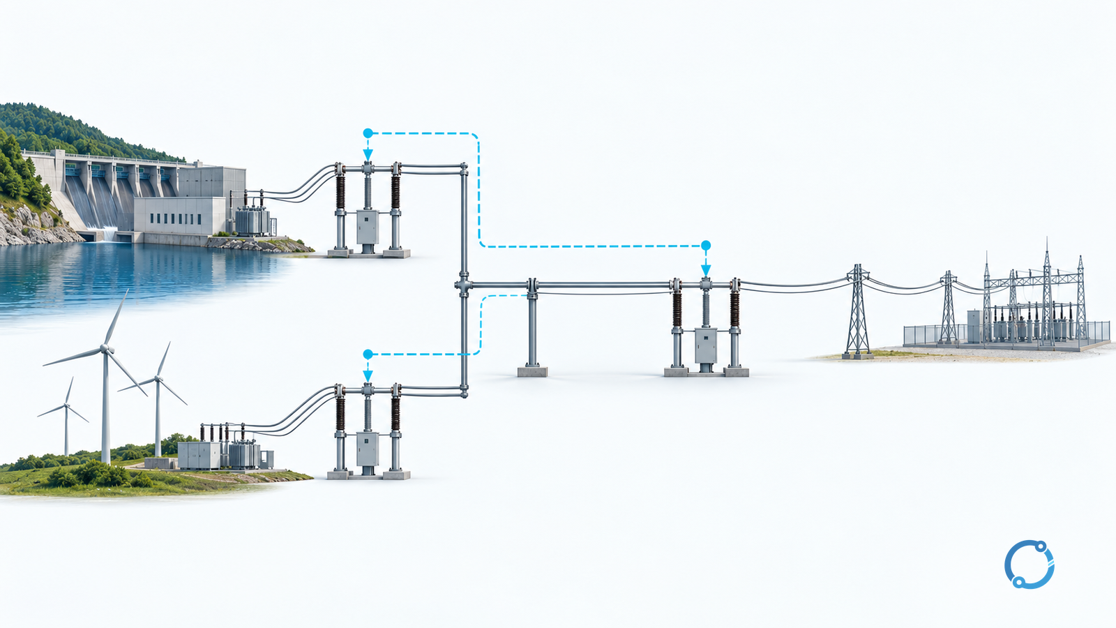
Remote backup, local backup and breaker-failure protection address different failure paths. Remote backup detects the fault from another location and clears it through other breakers. Local backup supplies another protection path at the protected installation. Breaker-failure protection acts when a commanded breaker has not cleared the fault and other breakers must isolate its remaining feeds.
The deciding question is not “Which backup is best?” It is which failed component must the system survive? Another relay that trips the same breaker can cover a detection failure, but it cannot make a failed interrupting device clear current.
This comparison is for protection engineers reviewing AC line and substation schemes. It uses conceptual topology, not construction wiring, and provides no universal breaker-failure timer or ready-to-load logic.
Compare on a common failure basis
For this article, “local backup” means an additional local fault-detection and tripping path. It is a broader term in some protection literature: breaker-failure protection itself is often described as a form of local backup. State that terminology in a design specification before comparing equipment.
Use the same dimensions for each strategy:
In the matrix, CT means current transformer, VT means voltage transformer, and DC means direct current.
| Review dimension | Remote backup | Local backup detection path | Breaker-failure protection |
|---|---|---|---|
| Starting information | Fault quantities measured at another location | Fault quantities available at the local installation | A defined initiation condition and evidence that clearing has not occurred |
| Main failure addressed | Local primary protection does not clear a fault that remains detectable remotely | One local detection or logic path is unavailable | The assigned breaker fails to clear when called upon |
| Normal clearing destination | Remote source or adjacent-network breakers | Usually the assigned local breaker through the backup path | Other breakers that remove contributions through the failed breaker |
| Principal dependency to review | Fault visibility, reach, sensitivity, system configuration and timing | Shared CT/VT inputs, DC supply, software/configuration and trip chain | Initiation, current/status supervision, timer logic and correct isolation destinations |
| Important limitation | Some faults or source conditions may not be adequately visible at the remote location | Does not solve a physically stuck breaker merely by repeating its trip | May not act for a primary relay failure that never produces a valid initiation |
| Acceptance evidence | Fault studies showing coverage and clearing consequences across allowed configurations | Independent-path review and appropriate functional tests | Successful-clear reset, failed-clear operation and trip-destination verification |
A local path is not independent merely because it occupies another enclosure. The IEEE PSRC report on redundancy in power-system protection discusses shared measurement, power and tripping dependencies. Its historical report is useful for reasoning about failure paths, not a source of current universal regulatory requirements.
Trace every contribution through the failed breaker
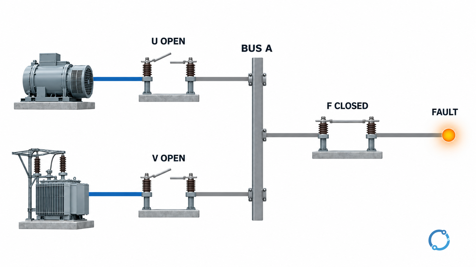
Consider an intentionally simplified bus A with two sources connected through breakers U and V. A feeder connects through breaker F. The feeder fault lies downstream of F.
Under successful primary operation, F opens and removes the faulted feeder from bus A. If F remains conducting after a valid trip, opening only U is insufficient while V still supplies the bus. The isolation study must account for both source paths.
This is a topology exercise, not a statement that every bus scheme must trip precisely those two breakers. Bus sectioning, transformer branches, embedded generation and remote infeeds can change the actual isolation set.
Use the substation trip-circuit verification guide for the separate command-to-coil path. Coverage of a fault and integrity of a trip circuit are related checks, not the same check.
Do not substitute breaker indication for interrupted current
A breaker auxiliary contact supplies mechanism/status information. It does not by itself establish that all fault current has been interrupted. Conversely, a current-only decision may need special treatment for low-current conditions or nonfault trips. The correct supervision depends on the scheme’s intended duties.
The current official IEEE C37.119-2025 catalog identifies breaker-failure detection and electrical isolation within the guide’s scope and shows that it supersedes the 2016 edition. The public scope page is not a substitute for the complete design guide or a relay-specific approved logic specification.
For a scheme review, distinguish at least these states:
- A valid command is followed by successful clearing: the failure sequence must not unnecessarily isolate healthy sources.
- A valid command is followed by persistent fault contribution: the defined backup isolation sequence must occur.
- The primary detection path fails without a trip command: identify which independent protection can detect and clear the fault.
- A status signal is wrong or unavailable: document the response rather than assuming normal indication.
- A transfer-trip channel is unavailable: determine what coverage remains and whether the operating state is still permitted.
These are test objectives. They are not Boolean equations to copy into a relay.
Judge remote backup by what it can actually see
Remote backup coverage changes when the fault quantity seen by the remote relay changes. Source strength, fault impedance, line topology and intervening contributions matter. For distance-based backup, the relay’s apparent impedance and permitted reach need study; a drawing’s physical line length is not enough.
The separate current and voltage transformer selection guide addresses measurement suitability. Backup coverage still requires the appropriate fault study and actual relay characteristics.
Compare the total clearing outcome, not only a relay delay. Include detection, logic and communications where used, breaker interruption and the resulting loss of healthy circuits. A faster but incorrectly addressed backup trip can remove the wrong part of the system.
Finish with a failure-coverage record
For each credible failure, write down the surviving measurement path, the surviving trip path, the breakers that will remove all relevant contributions, the clearing-time basis and the evidence that proves the sequence.
Use “unresolved” when a shared dependency defeats the assumed coverage. Do not hide a single DC fuse, common trip coil or shared measurement failure behind the phrase “dual protection.”
Approved functional testing should address intended operation, restraint/reset after successful clearing, applicable low-current duties, missing signals, communications dependencies and restoration after tests. Qualified personnel must control testing because a protection command can operate live plant even when the test stimulus is simulated.
When investigating an actual event, preserve the record before restoration; substation breaker-trip troubleshooting covers that different task. For a new design, the comparison is complete when every claimed backup has a named failure it survives and a demonstrated clearing path—not merely another relay on the bill of materials.