
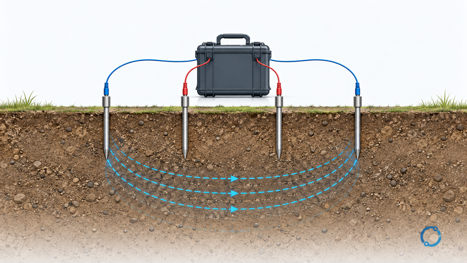
Earth-electrode testing begins by identifying the quantity you need: soil resistivity, electrode resistance or impedance to remote earth, bonding continuity, or surface potential during a defined condition. These are not interchangeable readings, and one low resistance number does not establish that an installation is safe.
Use a soil-resistivity survey to characterize the ground for a design model. Use an appropriate electrode test to investigate the installed network. Then compare the evidence with the project’s protection and earthing criteria, not a universal “good earth” target.
This is a measurement-planning and interpretation workflow for qualified electrical personnel. It does not authorize disconnecting an in-service protective conductor, carrying out uncontrolled current injection, or certifying compliance from a short article.
Fix the standards and acceptance boundary first
As checked on 7 October 2026, BSI lists BS 7430:2026, Protective earthing of electrical installations — Code of practice, published on 26 May 2026. The previous 2011+A1:2015 edition should not be presented as the current release.
The official IEEE 81-2025 scope includes earth resistivity, grounding resistance/impedance, surface potentials and measurement limitations. It supersedes IEEE 81-2012.
These catalog checks establish edition and scope only. They do not show that every clause of the paywalled standards has been reviewed, or that a particular installation complies. State the edition actually specified by the project, its jurisdiction and the applicable acceptance criteria.
Select the test from the question
| Engineering question | Quantity and usual unit | Measurement approach to consider | What the result does not prove |
|---|---|---|---|
| What soil model should inform an electrode design? | Apparent soil resistivity, Ω·m | Four-probe survey over planned spacings and directions | Installed electrode resistance or a complete layered-soil model from one point |
| What is the electrode network’s connection to remote earth? | Resistance or impedance, Ω | Appropriate fall-of-potential or other validated grounding-system method | Acceptable touch/step voltage under every fault |
| Is a metal bonding path continuous? | Resistance, usually Ω or mΩ | Approved continuity/bonding test | Resistance of soil around the electrode |
| Are accessible locations exposed to unacceptable potential differences? | Surface, touch or step voltage, V | Specialized study and appropriate measurement method | A safe result from an electrode resistance number alone |
Insulation-resistance testing measures a different property: leakage through an insulation system. A high insulation-resistance reading cannot replace an earth-electrode measurement.
Before driving probes, review underground services, access permissions, weather and site restrictions. The test plan must address transferred potential, induced voltage, electrical noise and the consequences of any proposed bond isolation. Equipment, leads and personnel protection must suit the actual exposure.
Check the soil-resistivity calculation
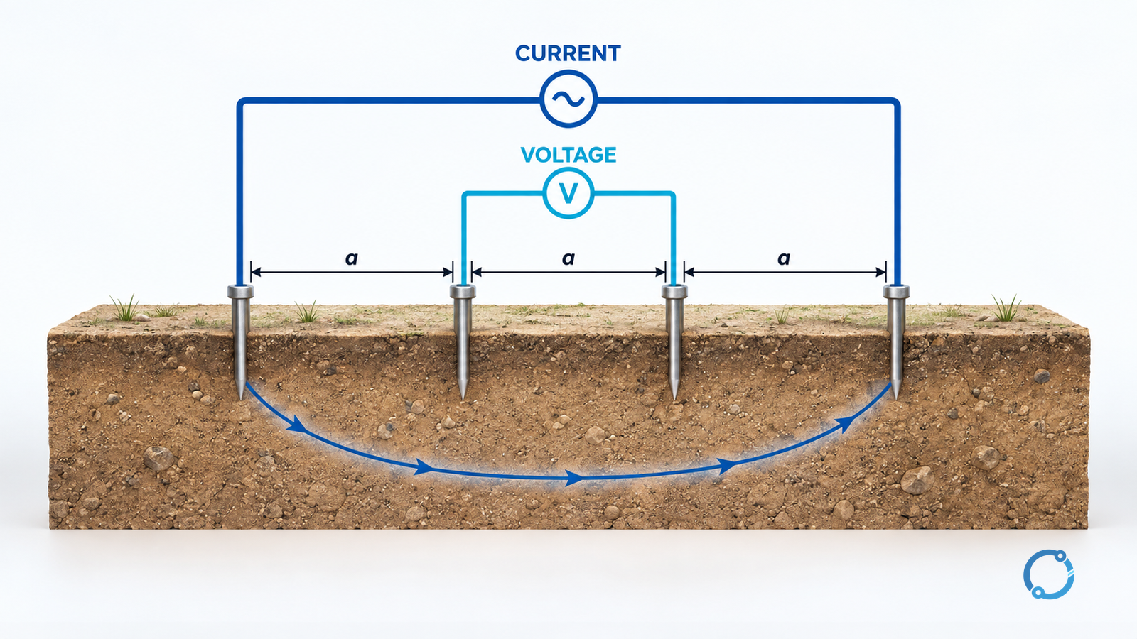
The idealized Wenner arrangement uses four shallow probes in a straight line with equal adjacent spacing a. Current is injected through the outer probes; voltage is measured between the inner probes.
With probe depth small compared with spacing, the simplified relationship is:
ρa ≈ 2πaR, where R = V ÷ I
ρa is apparent resistivity in Ω·m, a is spacing in metres, V is measured volts, I is injected amperes, and R is the instrument’s transfer-resistance result in ohms. That R is not the installed earth electrode’s resistance.
The historical government handbook MIL-HDBK-419A, Volume I, section 2.4.2.2, describes the equal-spacing method and its shallow-probe approximation. Treat this as measurement theory, not current installation requirements.
For an explicitly hypothetical reading at a = 2 m and R = 8 Ω:
ρa ≈ 2π × 2 × 8 = 100.53 Ω·m
At a hypothetical a = 4 m and R = 5 Ω:
ρa ≈ 2π × 4 × 5 = 125.66 Ω·m
Although the resistance reading decreased, the apparent resistivity increased because the geometric factor changed. Neither number is an installation pass/fail result.
A survey record should retain spacing, probe depth, direction, coordinates, instrument/test settings and environmental conditions. Do not assign each spacing to one exact soil depth or average all readings into a uniform model without justified interpretation. Where the shallow-probe approximation is unsuitable, use the appropriate correction or method.
Validate a fall-of-potential result before accepting it
An electrode test needs a known injection path, a sufficiently remote current probe and a potential-probe survey appropriate to the electrode’s extent. Keep the probe geometry and system connection state with the result.
The familiar approximately 62% potential-probe position follows an idealized geometry. It is not a universal location for large grids, interconnected electrodes or uncertain electrical centers. The historical handbook’s section 2.7.2 explains why spacing and electrode extent affect the reading.
The reviewer should therefore ask whether nearby potential-probe readings and a suitable change in current-probe location support a stable interpretation. A convenient single reading cannot establish a valid remote-earth reference. If restricted space prevents a valid setup, record the limitation and select a justified alternative rather than declaring a pass.
Keep parallel paths and safety in the same test plan
A connected network can return test current through other electrodes, cable screens or bonded structures. Decide whether the test question concerns an individual electrode or the complete connected system before interpreting the number.
If separating paths is necessary, it requires an approved safety and restoration plan. The National Weather Service grounding guidance specifically warns against disconnecting its multi-grounded neutral while site AC power remains on. That is a communications-site instruction, not a generic invitation to lift other bonds.
Do not improvise a test by disconnecting protective earth or an energized neutral. If isolation cannot be made safe, the method and interpretation must change. A measurement should never remove a protection function merely to produce an apparently cleaner number.
Make the acceptance record usable
Keep the measurement question, applicable edition, system connection state, layout, raw readings, validity checks, uncertainty/limitations and the qualified reviewer’s decision together.
Use these decision gates:
- Invalid or incomplete geometry: repeat or change the method; no acceptance conclusion.
- Valid result but unlike the design model: investigate configuration, soil conditions and model assumptions.
- Criterion exceeded: refer to the responsible designer for corrective action and re-verification.
- Resistance criterion satisfied but safety study unresolved: retain the open item; do not certify the whole earthing system.
For substations, protection duration and equipment interfaces affect the broader safety assessment. The separate CT installation, earthing and testing guide addresses a different bonding and measurement interface.
The useful deliverable is not simply “earth resistance = x Ω.” It is a traceable result that answers a defined question and states what remains unproven. That boundary is especially important when old formulas and a newly revised code of practice appear in the same project.