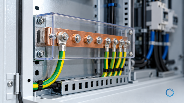
Short answer
Grounding, called earthing in IEC terminology, is the intentional connection of a specified part of an electrical system or installation to the earth. System grounding fixes the relationship between the source and earth. Equipment grounding connects exposed conductive parts to a protective path. Bonding connects conductive parts so they remain at substantially the same potential.
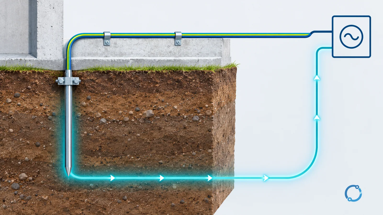
Grounding does not make fault current disappear into an unlimited earth sink. A fault circuit must still return to its source. The purpose of the protective path is to make that return path predictable and low enough in impedance for the protective device to operate within its intended time. If the loop is incomplete or too high in impedance, a person inside the installation enclosure may become part of the path before the overcurrent device responds.
This article uses the general IEC distinction between TN, TT and IT arrangements. It does not reproduce every national installation rule. The applicable code, supply authority requirements and an engineered protection study control the actual design. For system-level grounding of an industrial power network, IEEE 3003.1 describes recommended practice for industrial and commercial systems, while IEC 60364-1 defines the scope and fundamental principles of the low-voltage installation series.
The words that are often mixed up
| Term | What it connects | What it does not mean |
|---|---|---|
| System grounding | A defined point of the source, often the neutral, to earth | It does not automatically ground every enclosure or every metal part in the building. |
| Equipment grounding | Exposed-conductive-parts, such as an enclosure or frame, to the protective conductor or earth reference | It is not intended as a normal current-carrying conductor. |
| Bonding | Metal parts are connected together to create an equipotential path | Bonding does not by itself establish a connection to earth. |
| Earthing electrode | A conductive connection to the soil or another earth reference | An electrode is not a substitute for the protective conductor and bonding system. |
These functions often appear together, which is why the terminology can blur. A typical low-voltage installation may have a grounded source, a protective conductor connected to exposed metal, and bonding across metallic services and structural parts. Each element answers a different question.
Why grounding is part of a protection system
Grounding supports four related functions:
- It gives the electrical system a defined voltage reference.
- It provides a fault-current path that enables protective devices to operate.
- It limits touch voltage on accessible metal during a fault.
- It gives surge current a controlled path to the earthing system, within the limits of the surge-protective design.
The first function is a reference, not an emergency sink. Ungrounded systems can still have capacitance to earth and can develop unexpected voltage relative to earth. A grounded system makes the intended normal relationship explicit.
The second function depends on the complete loop. Consider a line-to-enclosure fault. Current leaves the source through the faulted line, reaches the enclosure, and must return through the protective conductor, earth path or another intentional route to the source winding. The impedance of the complete loop, not just the resistance of a local earth rod, determines the fault current.
The third function is why bonding matters. If two accessible metal parts are at very different potentials during a fault, a person touching both can receive a shock. A bonding conductor reduces that difference. It does not remove the need for fast fault clearing, and it does not guarantee that every touch voltage will be safe under every fault.
The fourth function is relevant to surge protective devices and lightning protection. A surge protector needs a suitable reference and a low-inductance path to do its intended job. That does not mean a surge protector is a substitute for the grounding and bonding design. It is one coordinated part of it.
Grounding and protection also have to be inspected as a system. A perfectly continuous protective conductor is of little value if the source point is not the point the designer intended, if a bonding connection has been removed during a renovation, or if the overcurrent device cannot respond within the required time. Conversely, a protective device with the correct rating cannot compensate for a missing fault path. The design, installation and verification records should tell one consistent story.
A note on the word “earth”
Earth is not a perfect conductor with zero resistance. Soil has resistivity, moisture and temperature-dependent behavior, and the earth return path can be physically large. An earth electrode establishes a local connection, but current must still find a route back to the source. In a TT arrangement, the return path is intentionally through the earth. In a TN arrangement, a metallic protective conductor provides the low-impedance route.
This distinction explains why a single local earth rod is not automatically a complete fault-protection scheme. The question is not only “is this metal connected to earth?” but also “what is the complete fault loop, what current will flow, and which protective device will operate within its designed time?”
Worked fault-path comparison: TN and TT
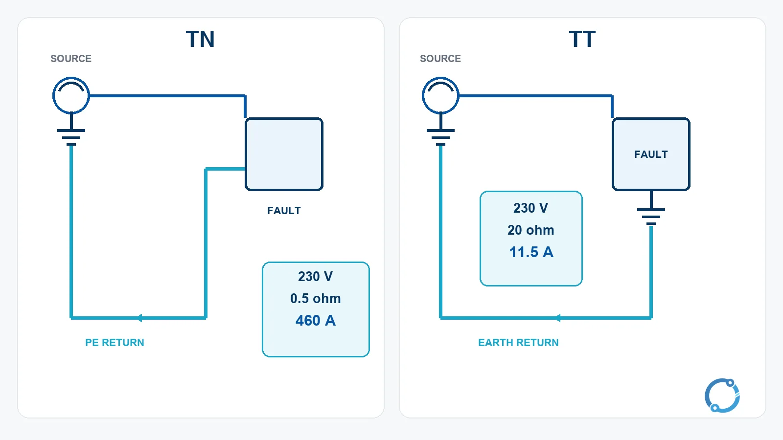
The following values are hypothetical teaching inputs, not installation settings. They show why the same supply voltage can produce very different fault behavior.
TN example
Assume a 230 V source, a line-to-enclosure fault, and a TN protective path with a total fault-loop impedance of 0.5 ohm. Using Ohm’s law:
I_fault = V / Z = 230 / 0.5 = 460 A
The result is 460 A. A 32 A overcurrent device is expected to operate in its fast magnetic or instantaneous region for a current that is many times its rating, although the exact trip point must be checked on the device’s time-current curve. The low-impedance metallic return path is the reason this arrangement can produce a large fault current.
TT example
Now assume the same 230 V source and a TT arrangement whose fault path returns through the earth with a total loop impedance of 20 ohm:
I_fault = 230 / 20 = 11.5 A
The current is 11.5 A. A 32 A overcurrent device should not be expected to clear this fault promptly through its normal overcurrent element, because the fault current is below its rating. TT installations therefore commonly use a residual-current device (RCD) or ground-fault circuit protection to detect residual current and disconnect the circuit. The exact device type, sensitivity and disconnection time depend on the installation rules and the system design.
For an introduction to residual-current versus ground-fault protection, see GFCI versus AFCI and the RCD types guide. Those pages explain device behavior; they do not replace a fault-loop study.
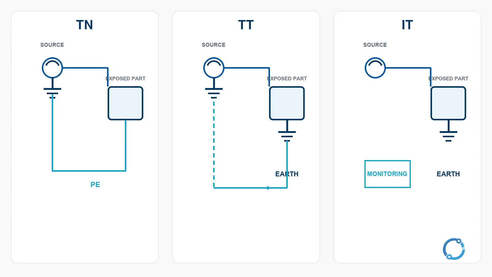
TN, TT and IT arrangements
| Arrangement | Source connection to earth | Exposed-conductive-part connection | Main fault-return idea |
|---|---|---|---|
| TN-S | Source neutral is earthed. | Exposed parts connect to the source earthed point through a separate protective conductor. | Metallic PE provides a low-impedance fault path. |
| TN-C | Source neutral is earthed. | Protective and neutral functions are combined in a PEN conductor along the affected section. | The combined conductor provides the return path, subject to strict rules. |
| TN-C-S | Source neutral is earthed. | A combined PEN is split into separate neutral and protective conductors at a defined point. | The fault path is metallic after the split; the transition must be designed correctly. |
| TT | Source neutral is earthed. | Exposed parts connect to a local earth electrode, not to the source’s protective conductor. | Fault current returns through the earth; residual-current protection is commonly needed. |
| IT | Source is unearthed or connected to earth through a high impedance. | Exposed parts are earthed, usually independently or in groups. | A first earth fault may be allowed to continue with monitoring; a second fault can create a dangerous loop. |
The labels describe the relationship between the source and the exposed-conductive-parts. They do not by themselves prove that an installation is safe. Conductor sizing, protective-device characteristics, equipotential bonding, fault-loop impedance, insulation monitoring and maintenance all matter.
Protective earth and functional earth are not the same job
A protective earth exists to support electrical safety. It provides a path for fault current, controls touch voltage and supports the operation of protective devices. Its continuity and connections are safety-critical, so it must not be treated as a convenient spare conductor.
A functional earth is provided for equipment operation, measurement, screening or signal reference. It may be needed for electromagnetic compatibility, instrumentation accuracy or a communications interface. It is not automatically suitable as a protective conductor, and a functional earth connection does not prove that the equipment enclosure is safely bonded. The two functions can share a designed earthing system, but the design must show that sharing does not compromise the protective path.
This distinction is especially important in control panels, instrumentation cabinets and systems with shielded cables. A shield connected at one end for signal reasons is not interchangeable with the protective bonding of an enclosure. The purpose, current rating, fault behavior and connection point must be documented.
The TN variants in plain language
TN-S uses a separate protective conductor from the source to the equipment. This makes the protective path easy to identify and test, but it requires a dedicated conductor throughout the installation.
TN-C combines neutral and protective functions in a PEN conductor. It can reduce conductor count, but it also creates strict requirements around the PEN path, disconnection and the locations where combined and separate functions may transition. A PEN conductor is not an ordinary neutral that can be switched or interrupted without understanding the protective function.
TN-C-S begins as TN-C and later separates neutral and protective conductors. The split point must be arranged so the protective conductor is not compromised by a neutral interruption. The existence of the label does not tell a maintenance worker where every conductor goes; as-built documentation and verification remain necessary.
Earthing electrodes and soil
An earth electrode is the conductive element that couples the installation to the surrounding soil or another earth reference. Its performance depends on the electrode geometry, installation depth, soil resistivity, moisture, temperature and nearby buried metal. A measurement made in dry conditions may not describe the same installation after a seasonal change.
Earth resistance is therefore a measured and maintained property, not a universal number copied from a table. Test methods and acceptance criteria must follow the applicable design and verification standard. The earth-electrode and soil-resistivity measurement guide and the earth-fault loop impedance testing guide cover the measurement side. This article does not state a universal “must be below X ohm” limit because valid criteria vary by system arrangement, protective method and jurisdiction.
Medium-voltage neutral grounding is a separate design task
At medium voltage, the choice between an isolated neutral, a resonant-earthed neutral, a resistance-earthed neutral and a solidly earthed neutral changes fault-current magnitude, overvoltage behavior and protection strategy. Those choices are not interchangeable with the low-voltage TN/TT/IT labels.
The medium-voltage neutral-earthing selection guide explains that design problem. The key point here is that “grounded” is too broad a word to describe a complete medium-voltage system. The neutral arrangement, cable capacitance, relay settings and permissible fault duration must be considered together.
What verification should establish
A grounding and bonding inspection starts with the system arrangement. The inspector needs to know where the source is earthed, which conductors serve as neutral and protective paths, where a PEN conductor is split, and which exposed metal is intentionally bonded. A drawing that only says “earth” without identifying the source return path is not enough to verify protection.
The next check is continuity and connection quality. Protective conductors and bonding jumpers should be continuous, correctly terminated and protected against loosening or corrosion. A visual check can find a missing connection, but it cannot establish that the conductor is electrically continuous through every joint. That requires an appropriate test and a comparison with the design.
Fault-loop impedance and protective-device response are then assessed together. The test or calculation must represent the fault paths that the design intends to clear, including the source, transformer, conductors and protective path. A measured value without the corresponding device characteristic does not answer whether the fault will be cleared in time.
For earth electrodes, the inspection should establish that the electrode is present, accessible where required, connected to the intended system and measured using a suitable method. Seasonal conditions matter, so a single reading should be interpreted with the design basis rather than copied into a generic rule.
Finally, the results must be recorded. Labels, drawings, test records and inspection schedules allow the next person to understand what was installed and what has changed. Grounding is not a one-time accessory that becomes permanently valid after commissioning.
Bonding is not optional bookkeeping
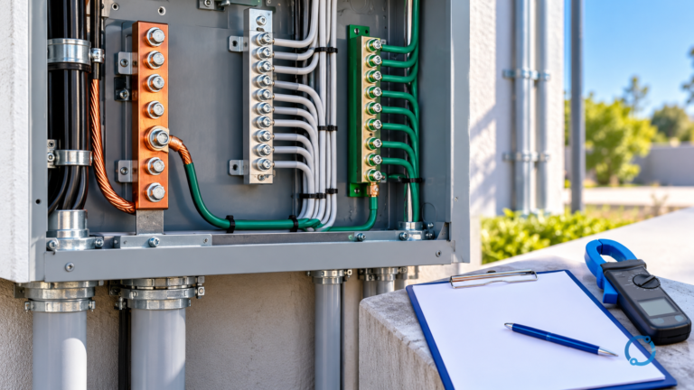
Bonding is the deliberate connection of conductive parts to create an equipotential zone. Main protective bonding may connect metallic water, gas or structural services at the point where they enter the installation. Supplementary bonding may reduce potential differences in a particular location. The correct conductor size and connection method depend on the installation rules and the available fault current.
The main bonding jumper sizing checks page explains the sizing logic for one specific protective arrangement. It is not a universal answer for every bonding conductor. Bonding must be inspectable, mechanically secure and protected against corrosion where the environment requires it.
Surge protection and the earthing reference
A surge protective device is designed to divert transient energy and limit the voltage across the equipment it protects. Its performance depends on the surge path, lead length, bonding and the earthing reference. A protector with an excellent terminal rating but a poor connecting path may not deliver the intended voltage at the equipment terminals.
The SPD selection by TN/TT/IT arrangement page covers that relationship. The SPD fundamentals article explains MOV and GDT behavior. Neither article changes the basic rule: a surge protector is part of a coordinated earthing and protection design, not a replacement for it.
Common misreadings
The first misreading is that the protective conductor carries current during normal operation. In a correctly designed system, it should not be used as a normal load-return conductor. If it carries continuous current, there is an unintended parallel path, a wiring error or an insulation problem that requires investigation.
The second is that a lower earth resistance automatically makes every installation safe. Earth resistance is one input. Fault-loop impedance, conductor continuity, protective-device response, touch-voltage duration and bonding determine whether the protection works as intended.
The third is that an isolated earth rod is a complete protective system. An earth connection that does not provide a return path to the source may create a local voltage reference but cannot be assumed to clear a line-to-enclosure fault. The path and the protection must be designed together.
Frequently asked questions
Does fault current disappear into the earth?
No. Earth is part of a circuit. Current must return to the source, whether through a metallic protective conductor, the earth, the supply transformer winding or another intentional path. The impedance of that complete path determines the current.
Is bonding the same as earthing?
No. Bonding connects conductive parts to reduce potential differences. Earthing connects a specified part of the system to earth. The two functions often work together, but one does not automatically provide the other.
Why does a TT arrangement often need an RCD?
A TT fault may return through a relatively high earth impedance, so the resulting current may be too small to operate an ordinary overcurrent device promptly. A residual-current device can detect the current imbalance and disconnect the circuit within its designed characteristics.
Is TN always better than TT?
No. Each arrangement has different fault-current, protection, supply and maintenance implications. The correct choice depends on the supply system, installation rules, load requirements, earth conditions and the protection study.
Does a surge protector make grounding unnecessary?
No. A surge protector needs a suitable reference and a controlled transient-current path. It supplements the earthing and bonding system; it does not replace it.