
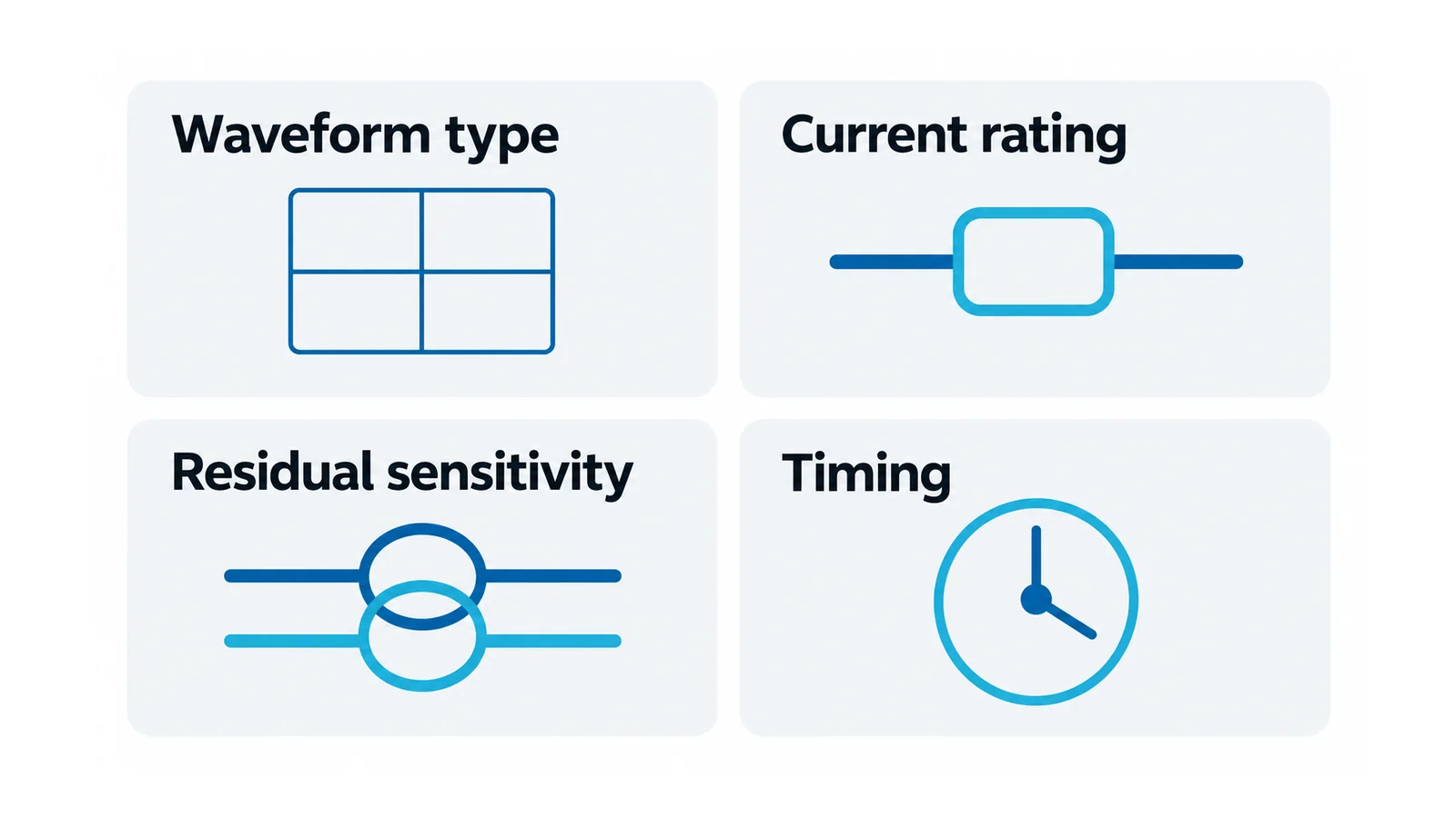
Select a residual-current device (RCD) by the residual-current waveforms that the connected equipment can produce, then verify its current rating, residual sensitivity, timing and installation compatibility. Type AC, A, F or B is not the circuit’s ampere rating and is not a substitute for those other checks.
Electronic loads make that distinction important. A device that responds to sinusoidal AC residual current may not provide the required response when a fault involves pulsating or smooth DC, or specified mixed-frequency currents. Equipment name alone is insufficient: identify the converter arrangement and the protection required by its instructions and applicable installation rules.
This guide uses IEC-oriented terminology for AC low-voltage installations, primarily household and similar RCD product families. Industrial residual-current protection may use different product routes. It is a selection framework for competent designers, not a wiring procedure or a universal rule for every country.
Start with the residual current—not the load current
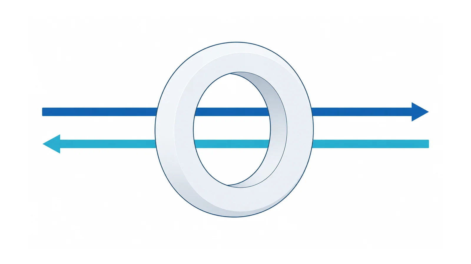
An RCD evaluates the imbalance among the intended current-carrying conductors passing through its sensing system. Current returning through another path can create a residual current even when the normal load current remains well below the circuit’s overcurrent rating.
For a simple illustrative single-phase instant, suppose 10.000 A leaves and 9.985 A returns through the intended paths. Their difference is 0.015 A, or 15 mA. This is a balance example, not a claim that an arbitrary RCD must trip at 15 mA. Actual response depends on waveform, magnitude, time and device characteristics.
An RCD does not make every electric shock impossible. A current path between live conductors can leave the measured currents balanced. Earthing, bonding, overcurrent protection, isolation and safe work practices remain necessary.
US Class A GFCI terminology is a different classification system; it must not be equated with IEC Type A. The GFCI-versus-AFCI guide explains that separate US hazard and device comparison.
Separate product form from waveform response
An RCCB is a residual-current operated circuit-breaker without integral overcurrent protection. Its current rating does not mean it will trip on an overload at that value. It requires the appropriate overcurrent protection and coordination for the installation.
An RCBO combines residual-current and overcurrent protection. Its residual-current classification still needs to be identified independently of its overcurrent characteristics.
The official scopes of IEC 61008-1:2024 and IEC 61009-1:2024 distinguish these household-and-similar product forms. A circuit-breaker-style housing or a TEST button does not tell you all the functions inside it.
What Types AC, A, F and B distinguish
Use this table to identify the response family to investigate—not to release a design without product and installation evidence.
| RCD waveform type | Principal response territory | Boundary to resolve |
|---|---|---|
| Type AC | Sinusoidal AC residual current | Not a general choice for unknown electronic/DC-producing loads; confirm whether its use is permitted locally |
| Type A | Type AC territory plus pulsating DC residual current | Pulsating DC response must not be mistaken for detection of arbitrary smooth DC |
| Type F | Type A territory plus specified composite residual currents associated with applicable single-phase frequency-converter arrangements | Not universal smooth-DC detection or a guarantee for every drive |
| Type B | Additional specified responses including smooth DC and defined frequency-related conditions | Still needs equipment, frequency, rating, coordination and installation compatibility checks |
The IET’s RCD-type explanation provides the waveform distinctions and warns against confusing RCD types with overcurrent breaker curves. Its 2019 installation-rule statements should not be treated as current requirements without checking later amendments.
IEC 62423:2009 specifies additional requirements and tests for Type F and Type B devices, used with IEC 61008-1 and IEC 61009-1. Its scope describes Type F applications involving specified line-to-neutral or line-to-earthed-middle-conductor frequency inverters. That is more precise than “all appliances with motors need Type F.”
On an RCBO, a B overcurrent curve and a Type B residual-current response are different attributes. Read the exact marking and documentation for both. Likewise, a time-delay/selective designation is another characteristic, not a fifth interchangeable waveform class.
DC tolerance is not smooth-DC detection
Some classifications specify operation with a limited smooth-DC component superimposed on another residual waveform. Tolerating that component while detecting the specified fault is not the same as detecting smooth DC on its own.
The IET’s July 2022 Wiring Matters guidance emphasizes this distinction for Type A and Type F. It also discusses how DC components can affect other RCDs in the installation. Do not simplify this into either “Type A detects all DC” or “any DC presence makes every Type A device ineffective.” The actual device conditions and fault arrangement matter.
For converters, identify the relevant AC-side residual fault behavior and any internal DC-detection/disconnection provision. Do not assume that a DC-output appliance requires an RCD designed to interrupt a standalone DC circuit. AC-side waveform suitability and DC-system switching are different engineering tasks.
Use a five-input selection record
| Input | Record before choosing | Why it changes the decision |
|---|---|---|
| Protection purpose and applicable rules | Circuit/use, jurisdiction, adopted edition and required protection | Determines sensitivity, disconnection and device-route requirements |
| Equipment and possible faults | Converter topology or documented residual-current behavior and equipment instructions | Determines which response class is suitable |
| Device characteristics | Product form, waveform class, rated current, residual operating current, poles and timing | Prevents one suitable attribute from masking another unsuitable one |
| Whole installation | Upstream/downstream RCDs, normal leakage and overcurrent/fault coordination | A correct final-circuit device does not prove the upstream arrangement is suitable |
| Verification basis | Exact device/equipment identity, accepted conditions and competent-person checks | Converts a generic type choice into an auditable application decision |
The order is deliberate. Start from the protection purpose and connected equipment; select the response class; then close the remaining rating and coordination checks. If fault-waveform information is missing, obtain it or refer the design to the responsible engineer. Do not guess from the motor’s kW value or the appliance category.
Current rating I_n is the declared load-current quantity; residual operating current I_Δn is a different quantity used in the protective response. A hypothetical marking of 40 A and 30 mA illustrates two separate axes, not recommended values for the reader’s circuit.
Example: replacing a load with electronic speed control
Suppose a hypothetical fixed load is replaced by equipment containing a single-phase speed controller. The existing RCD was selected for the old load, and no residual-current information has yet been provided for the replacement.
Hold the compatibility decision. Obtain the replacement equipment’s RCD requirements and converter/fault information; review the proposed device’s waveform response and conditions; then check upstream devices, normal leakage, sensitivity, timing and overcurrent protection. Type F may be relevant to a specified single-phase converter case, but the example does not prove it is suitable—or necessary—for the unspecified controller.
If the equipment is a drive, the VFD selection checklist helps establish the drive and system inputs. It does not replace the RCD compatibility evidence.
EV charging illustrates another important distinction: the required arrangement can depend on separate DC residual-current detection and disconnection. The IET’s 2024 EVSE guidance explains that dependency under its stated UK edition. Do not convert that example into a universal instruction for every EV charger, PV inverter or UPS, or assume that an equipment feature called “leakage protection” has the required evaluated function.
Verify the applicable edition and the installed function
RCD requirements are jurisdiction- and application-specific. As checked on 5 October 2026, the IET identifies BS 7671:2018+A4:2026 as published, with Amendment 3:2024 remaining valid during the transition until 15 October 2026. UK projects should establish their applicable design/verification basis rather than treating an older guidance article as the current rule. IET edition and transition guidance
Installation and instrument testing belong to competent personnel using the applicable procedures and device instructions. The built-in TEST function exercises its designed test path; it does not establish compatibility with every possible converter fault or inspect the whole installation. Insulation testing is a separate method with its own equipment-isolation limits, described in the insulation-resistance testing guide.
Selection is complete when the response class and all other protective characteristics are justified for the actual equipment and installation. Do not bypass the RCD, increase I_Δn to suppress repeated trips or substitute an ordinary breaker merely to restore operation. Resolve the underlying condition and preserve the required protection.
Sources
- IEC 61008-1:2024 and IEC 61009-1:2024: RCCB and RCBO public scopes.
- IEC 62423:2009: Type F/Type B additional requirements and application scope.
- IET — Which RCD Type?, September 2019: waveform terminology, not current installation clauses.
- IET Wiring Matters, July 2022: DC-component and selection boundaries.
- IET — RCDs for EVSE, May 2024: a scoped application example.
- IET — BS 7671 edition checker: current edition/transition check, accessed 5 October 2026.