
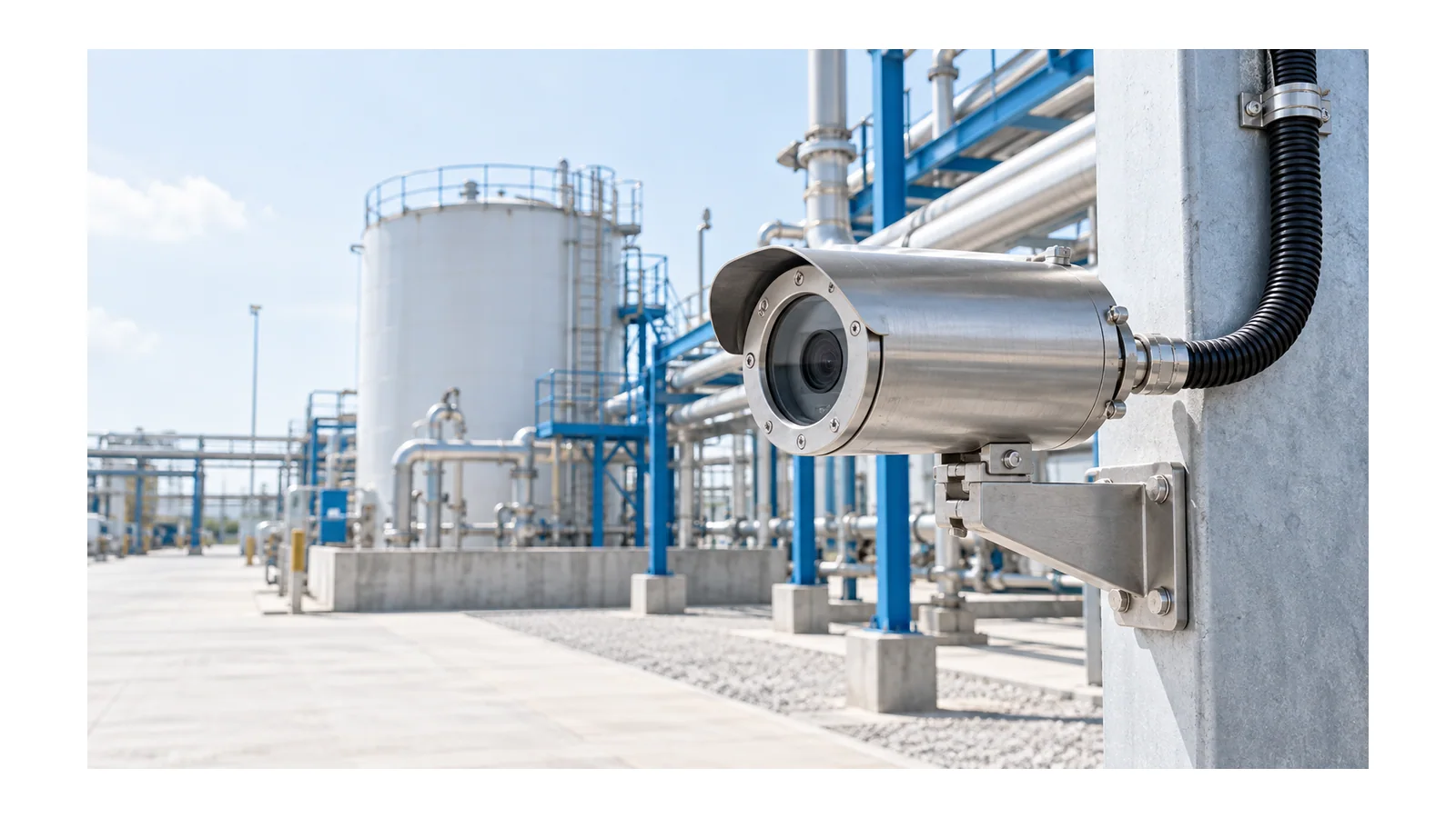
An ATEX camera is suitable for a Zone 1 or Zone 2 installation only when the complete installed configuration matches the classified atmosphere and its conformity evidence. Check the enclosure, camera module, optical window, thermal options, cable entries and power or network interfaces together. A certificate for an empty enclosure, a high ingress-protection (IP) rating or a low-voltage supply does not establish that the finished camera is acceptable.
The engineering outcome is a traceable camera specification: what it must see, where it will operate, which configuration is covered, and how the installation will be inspected. This guide concerns fixed cameras in gas-hazard locations under the EU ATEX framework. It does not classify an area, approve a product, or replace competent hazardous-area design and installation.
Start with the place and the viewing task
Obtain the current area-classification drawing and explosion-protection documentation. Record the zone at the camera’s actual location, the substance and gas group, the temperature basis, ambient conditions and installation constraints. Do not infer the classification from nearby equipment or assume that a camera mounted higher on a structure is outside the zone.
For gas hazards, the equipment-category selection basis in Directive 1999/92/EC, Annex II B is, subject to its risk-assessment provision:
| Classified location | Category basis for suitable gas equipment | Boundary to preserve |
|---|---|---|
| Zone 1 | Category 1 or 2, with appropriate gas designation | Category alone does not settle group, temperature or installation suitability |
| Zone 2 | Category 1, 2 or 3, with appropriate gas designation | Less frequent atmosphere does not mean ordinary equipment is automatically acceptable |
Zone 0 requires a different protection basis; do not extend a Zone 1 camera’s approval into it. Dust locations use a separate classification and equipment designation. Where gas and dust hazards coexist, assess both. OHELE’s hazardous-area lighting guide explains the underlying zone and marking distinctions; a camera needs additional assembly and imaging checks.
Define the image task at the same time. Monitoring a wide process area, reading an instrument, recognizing a person and inspecting a moving conveyor impose different optical requirements. Specify the target, distance, field of view, lighting, motion, required image detail and acceptable obscuration. A camera can satisfy the hazardous-area requirement and still fail its observation task.
Verify evidence for the camera, not just its housing
ATEX and IECEx are not interchangeable labels. The European Commission’s ATEX equipment guidance identifies Directive 2014/34/EU as the EU product framework, with essential requirements and conformity-assessment procedures. The applicable route depends on the equipment. Check the EU declaration of conformity, relevant assessment documents, marking and instructions rather than demanding the same certificate type for every category.
For an IECEx claim, verify the exact equipment identity, certificate issue and covered options against the official record. IECEx distinguishes complete-equipment, component and unit-verification certification. A component is not intended to be used alone and requires further assessment when incorporated into equipment. That distinction matters when a proposed camera combines a separately sourced enclosure, camera board, heater and power converter.
Ask which document covers that combination. Evidence for each loose part is not automatically evidence for the assembled product. Conversely, a camera supplied as an assessed complete equipment item should be compared with the covered configuration, not treated as an arbitrary collection of components.
An X suffix in an IECEx equipment certificate identifies specific conditions of use. Read them, assign responsibility for meeting them and retain the evidence. The IECEx Secretariat notice on the X suffix explains why essential use conditions cannot be ignored. Certificate conditions and the applicable installation rules both matter; one does not replace the other.
Put the assembly boundary on one drawing
A useful specification sketch separates the equipment boundary from the field installation and the external network. It should show what is supplied and assessed as one item, what is connected on site, and where options can change the thermal or protection basis.
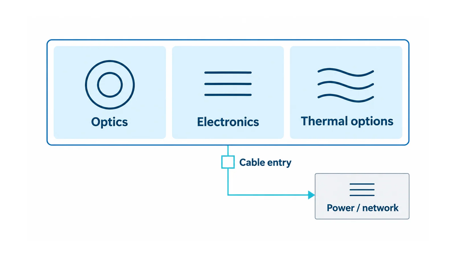
The following register turns that boundary into six review gates. These are engineering review questions, not six extra legal requirements.
| Gate | Application inputs | Evidence to retain | Do not release when |
|---|---|---|---|
| 1. Atmosphere | Actual location, zone, substance group, temperature basis | Approved classification and required marking schedule | Classification or temperature basis is unresolved |
| 2. Complete equipment | Exact camera variant, enclosure and installed options | Declaration, applicable certificates, configuration schedule and instructions | Evidence covers a different variant or only a component |
| 3. Thermal duty | Ambient extremes, solar exposure, heater, illuminator and movement duty | Permitted operating range and option combinations | A proposed combination is outside documented conditions |
| 4. Optical duty | Target detail, viewing distance, lighting, motion and window condition | Application image test or documented optical assessment | The required view cannot be demonstrated through the actual window |
| 5. Interfaces | Supply, network, entries, glands, connectors, bonding and mounting | Matching equipment instructions and installation design | An entry or connection is improvised or undocumented |
| 6. Lifecycle | Access, inspection, cleaning, replacement and change control | Initial-inspection plan and configuration-controlled maintenance record | Routine maintenance would alter the accepted protection arrangement |
Check thermal and optical options together
The base camera’s power demand is only one operating state. A heater, infrared illuminator, demister or motorized pan/tilt mechanism can change the installed duty. Obtain the permitted combinations and the power budget at the least favorable supply condition. Do not average away a start-up or simultaneous operating demand that the supply must support.
Neither “more cooling” nor a higher temperature-class designation is a substitute for checking the documented ambient range and complete configuration. If direct sun, an insulating deposit or an added accessory changes the assumed conditions, return the change to the responsible equipment and installation reviewers.
The optical window introduces a separate acceptance question. Check the view through the finished assembly, including reflections, contamination, condensation, illumination and the required spectral band. If infrared observation is required, verify that the actual window and optical arrangement support it. A clear-looking window is not proof of the required infrared performance.
For imaging acceptance, describe a reproducible task rather than a marketing resolution number. For example: identify the required feature on a moving target at the specified location, under the site’s defined lighting and window condition. Record the conditions and result. This is an application check, not an explosion-protection test.
Treat PoE and cable entries as engineering interfaces
Power over Ethernet (PoE) may combine power and communication in one cable, but it does not make the connected equipment intrinsically safe or suitable for a hazardous location. Determine whether PoE is a covered equipment option, how much power the complete camera requires, and whether the supplying port can support the specified duty. Do not insert an uncertified splitter or adapter inside the camera to solve a power-budget problem.
Record cable type, entry arrangement, glands or permitted connectors, unused-entry closure, bonding and mechanical support. A network switch in an unclassified area does not settle the suitability of the camera end of the cable. The installation design must address the whole interface.
IEC 60079-14:2024 covers Ex electrical-system design, equipment selection, installation, initial inspection, documentation and personnel competency within its stated scope. Use the edition and national rules applicable to the project. Its public scope is not a substitute for the full requirements or the exact equipment instructions.
Do not use a generic insulation-resistance test as a substitute for this review. OHELE’s insulation-resistance testing guide explains why test boundaries and connected electronics must be identified first. A test result cannot confer hazardous-area suitability.
Example: adding a heater after camera approval
Consider a hypothetical Zone 1 camera selected for a documented gas and temperature requirement. The original accepted variant has fixed optics and no heater. A later site review identifies winter condensation and proposes adding a heater and a different entry connector.
The change is not complete when the camera produces a clear image on a workbench. The review must establish:
- Whether the heater and connector are covered options for that exact equipment variant.
- Whether combined camera/heater duty remains within the permitted supply, ambient and thermal conditions.
- Whether the new entry arrangement meets the equipment and installation requirements.
- Whether the viewing task still passes in the site’s defined conditions.
- Which documents, inspection points and maintenance spares change.
If the combination is not covered, stop and obtain an appropriately assessed configuration or redesign the application. Do not claim that the enclosure certificate has approved the modification.
The final handoff is the classification reference, camera identity and option list, conformity evidence, conditions-of-use register, optical acceptance record and initial-inspection plan. That set of records makes camera suitability traceable. “ATEX camera for Zone 1” alone does not.