
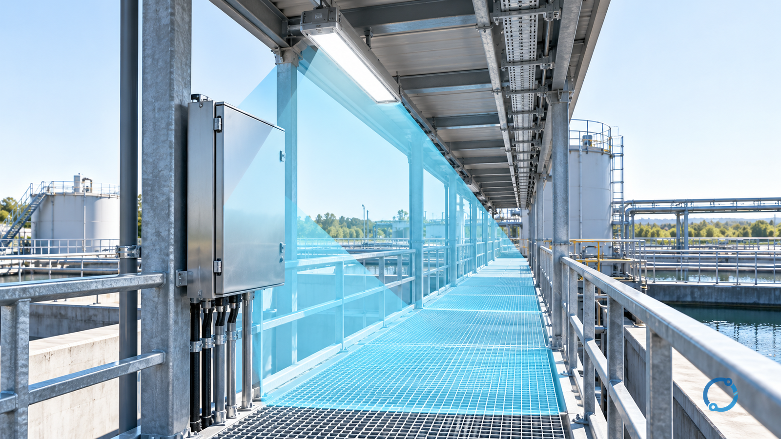
Select a hazardous-area linear LED luminaire in two stages: exclude configurations that do not meet the installation’s hazardous-area requirements, then compare the remaining configurations by their delivered light at the task. Wattage, total lumens and enclosure length alone cannot establish whether operators can see the intended work.
This is a photometric selection article for qualified industrial designers using an established hazardous-area classification. It does not classify the area or give a universal lux target. Begin with the existing ATEX lighting zones selection guide when the equipment eligibility basis is still unresolved.
Describe the visual task before comparing fittings
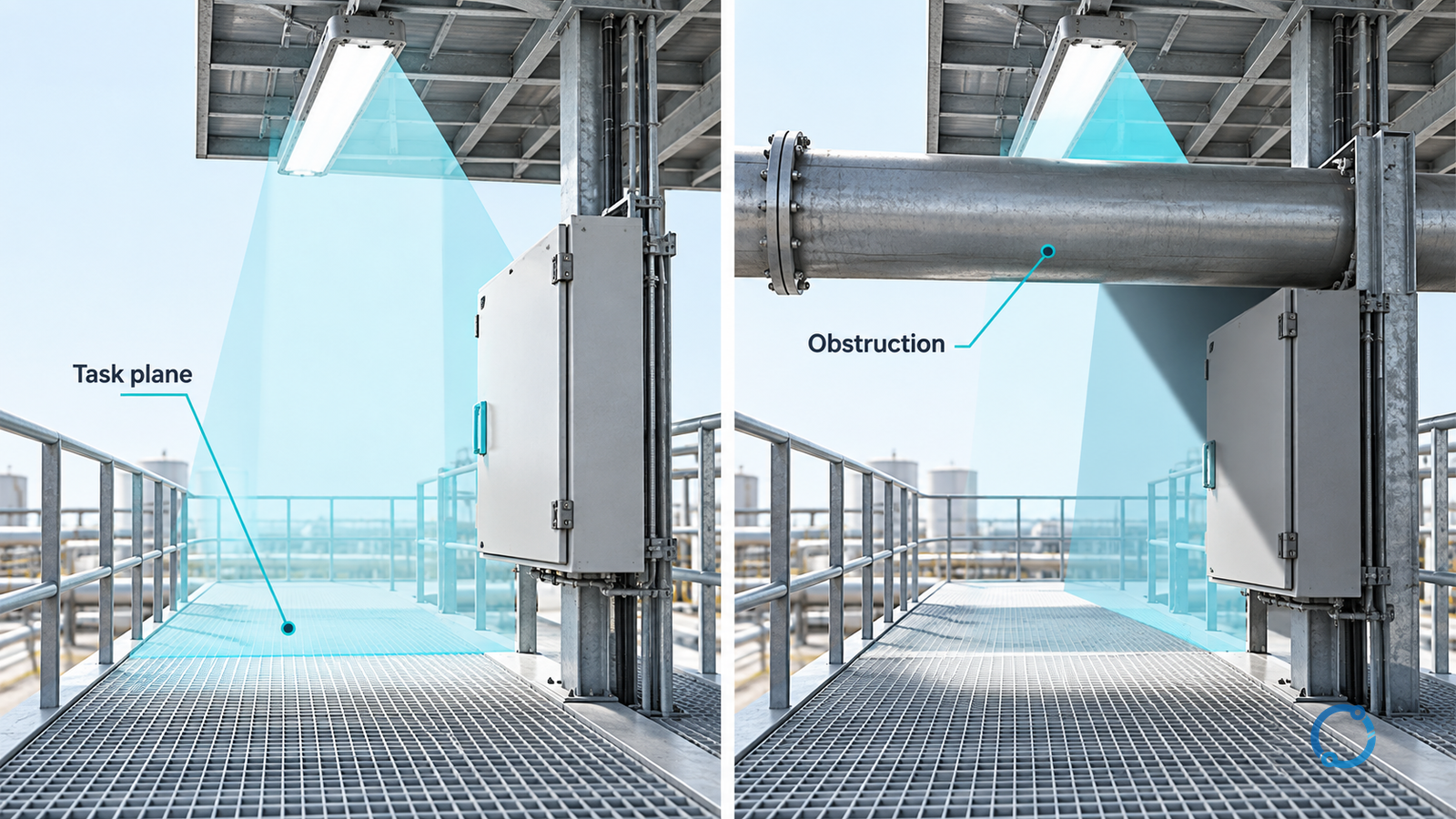
“Light the walkway” and “read a vertical instrument face beside the walkway” are different visual tasks. Record the relevant working plane, observer position, mounting arrangement, obstructions and operating conditions. A horizontal floor calculation cannot be assumed to demonstrate visibility on a vertical panel.
Prepare a layout showing the task surfaces and available mounting positions. Include fixed pipework, cable trays and structural members that can interrupt the light path. Do not accept a simulation based on a clear empty room when the installation contains substantial obstructions.
Define the required illuminance and other acceptance criteria from the applicable workplace or project lighting basis. This article supplies no substitute target. Emergency lighting and escape-route performance are separate requirements and must not disappear inside a general-lighting calculation.
Compare complete optical configurations
The U.S. Department of Energy’s industrial LED luminaire acquisition guidance advises comparing like products and considering light output and distribution. Its federal acquisition context is not hazardous-area certification, but the comparison principle is useful: evaluate the actual luminaire configuration, not an isolated LED package.
| Task input | Selection question | Evidence needed before acceptance |
|---|---|---|
| Horizontal and vertical task surfaces | Does the distribution reach the required planes? | Configuration-specific photometric calculation |
| Mounting height and orientation | Is the predicted pattern valid for the installation? | Actual mounting geometry and aiming |
| Obstructions | Are critical surfaces shadowed? | Layout model with relevant structures |
| Observer position | Could the source impair viewing? | Glare assessment appropriate to the task |
| Operating and ambient conditions | Is this output/configuration valid in service? | Applicable performance and approval documentation |
| Dirt and maintenance access | How will maintained performance be supported? | Stated maintenance assumptions and access plan |
The table is a proposed design review matrix. It is not a set of mandatory values extracted from a standard.
A wide distribution may suit a broad working surface but place unwanted light in an observer’s view. A narrower distribution may suit a defined task but leave adjacent surfaces underlit. Neither is inherently better: evaluate both at equal mounting conditions against the same task criteria.
Keep efficacy separate from task illumination
Luminaire efficacy is light output divided by electrical input power. It helps compare energy performance, but it does not say how much useful light reaches a particular surface.
Consider an independent hypothetical comparison: configuration A produces 6,000 lm at 50 W, and configuration B produces 6,000 lm at 60 W. Their efficacies are respectively 120 lm/W and 100 lm/W. The arithmetic favors A on that metric alone.
However, identical total lumens do not establish identical illumination at an instrument face. The distribution, mounting and obstructions still need to be evaluated. These invented values illustrate the comparison method; they are not product data, a hazardous-area rating or evidence of a completed design.
Even a correct efficacy calculation needs a consistent boundary. Use complete luminaire input and output on the same operating basis. Do not compare LED-chip efficacy with another product’s complete-luminaire efficacy.
Check glare and visibility without inventing a threshold
Glare cannot be reduced to “more lumens means better visibility.” DOE’s glare research overview identifies source position, size, luminance distribution and background conditions as relevant assessment variables. It does not provide a universal acceptable-glare number for every industrial walkway.
Specify the actual viewing task and an appropriate assessment method. Include positions where someone looks upward toward equipment, along a walkway or across a bright background. Where simulation does not answer the practical viewing question, plan a representative evaluation under an authorized safe-work arrangement.
Also separate color-related requirements from brightness. If the task depends on identifying a colored indicator or process condition, state that need in the specification. Do not assume that a nominal color temperature proves color discrimination or that a single rendering metric closes every visual task.
Protect the configuration boundary
An optical variant, driver setting or mounting accessory can change the configuration reviewed. Keep its identity consistent across the approval documents, photometric evidence and order schedule. Do not approve one version and procure another because the family name is the same.
IEC 60079-14:2024 addresses Ex installation design and selection, including initial inspection. Its public scope does not establish the eligibility of a particular linear fitting or allow a field alteration. Resolve those questions using the applicable installation basis and exact equipment documentation.
Thermal and environmental conditions belong in this configuration check. A light-output claim under one condition must not silently become a guarantee under another. Any limitation affecting the intended location should be made visible before candidates are compared on efficiency.
Release a task-based selection, not a wattage equivalent
The final selection record should tie together the eligible equipment configuration, task criteria, actual geometry, photometric evidence, maintenance assumptions and acceptance plan.
If a candidate passes equipment eligibility but fails the task-plane calculation, revise the layout or optical choice. If it meets the lighting task but lacks support for the hazardous location, reject it regardless of its efficacy. When both remain unresolved, do not treat a favorable wattage comparison as a tie-breaker.
The completed engineering outcome is a traceable statement that the selected configuration can serve the defined visual task under the stated conditions. A nominal “LED replacement wattage” is not that statement.