
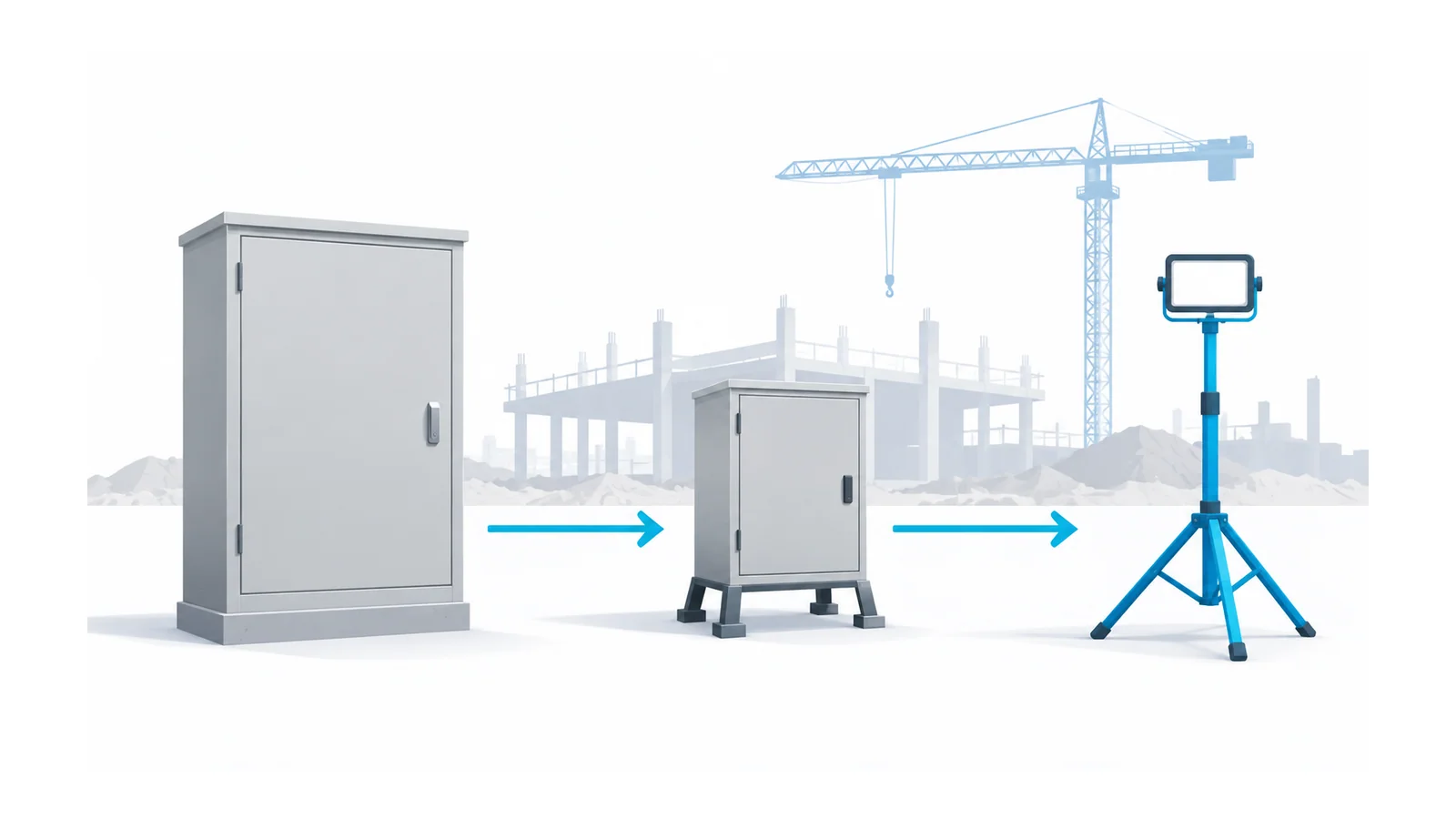
Temporary jobsite power needs a source-to-use verification record, not just a generator, extension cords and a ground-fault circuit interrupter (GFCI). Define the supply and load duty, verify distribution and protection, control cable routes and environmental exposure, authorize energization, then inspect changes and remove the installation when its purpose ends.
This workflow concerns low-voltage temporary electric power and lighting on U.S. construction sites. Federal Occupational Safety and Health Administration (OSHA) construction requirements and applicable, locally adopted National Electrical Code (NEC) requirements are separate checks. State-plan rules, local amendments, permits, utility requirements and equipment instructions may add obligations. The article is a planning and review framework for competent teams, not permission for unqualified electrical work or a certificate of compliance.
Establish which rules apply before choosing equipment
Record the authority having jurisdiction, applicable OSHA framework, adopted NEC edition, local amendments and the work being performed. A temporary installation inside an operating plant may involve different boundaries from a new construction site. Do not assume that construction rules automatically govern every maintenance activity.
For an edition-specific NEC navigation reference, Article 590 covers Temporary Installations in the 2023 NEC. The National Fire Protection Association (NFPA) official restructuring reference identifies that 2023 article and separately labels proposed future numbering. Proposals are not adopted requirements. Find the applicable temporary-installation provisions in the actual edition accepted for the job.
OSHA’s 1926.405(a)(2) modifies certain wiring methods for temporary use; it does not suspend the remaining permanent-wiring requirements of Subpart K. It also requires removal when construction or the installation’s purpose is complete. Plan the temporary system’s end state at its beginning.
Use five release stages, then control the lifecycle
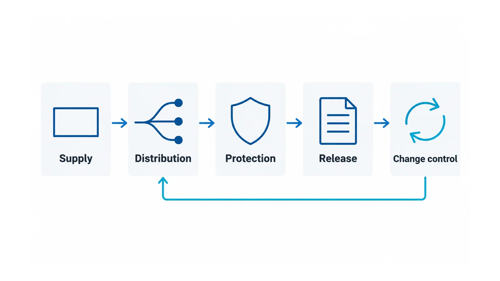
The following review structure is an editorial workflow, not a substitute for the adopted code or the employer’s procedures. Each stage needs an owner and evidence before the next stage relies on it.
| Stage | Required inputs | Review evidence | Stop condition |
|---|---|---|---|
| Supply | Utility, generator or other source; voltage; transfer arrangement; grounding/bonding basis | Source diagram and authorized connection design | Backfeed, source identity or bonding arrangement is unresolved |
| Loads and distribution | Load schedule, simultaneous operation, start-up duty, routes and equipment | Capacity, fault-duty and conductor/protection checks | Ratings are inferred from plug fit or nameplate kW alone |
| Shock and environment | Receptacle use, grounding path, protection method, water and damage exposure | Applicable protection record and approved equipment/route | Missing protection evidence or damaged equipment |
| Inspection and release | Installed configuration, isolation controls and competent personnel | Inspection/test record, deficiencies closed and energization authorization | Open safety defect or undocumented configuration change |
| Use, change and removal | Inspection responsibilities, source/load changes and completion date | Current register and controlled decommissioning plan | A change invalidates the accepted basis or the purpose has ended |
Identify the source, fault path and usable capacity
Start with a one-line diagram that identifies the source, disconnecting means, distribution points and final circuits. Include any transfer equipment and all alternative sources. A portable generator directly supplying cord-connected tools and a generator supplying a building through transfer equipment are different configurations.
OSHA’s portable-generator grounding fact sheet explains a limited frame-as-ground arrangement for generator-mounted or cord-and-plug loads when its stated bonding conditions are met. It separately addresses a generator supplying a structure through a transfer switch. Do not apply one arrangement’s exception to the other, and never improvise a backfeed connection.
The responsible electrician must establish the neutral, equipment-grounding and transfer arrangement for the actual system. A grounding electrode is not a replacement for an effective equipment-grounding conductor and fault-return path. Adding a rod without resolving the connection design does not complete this stage.
Build the load schedule by circuit and operating state. Include steady load, simultaneous tools, motors or compressors starting, lighting, trailers and any reserved capacity. Do not turn a generator’s headline rating into an automatic feeder or branch-circuit rating. OHELE’s circuit-breaker sizing explanation shows why current arithmetic alone does not establish protection suitability.
For equipment acceptance, OSHA 1926.403 requires approved equipment, use consistent with listing or certification instructions, sufficient interrupting rating, identification and suitable access or guarding. Record the actual supply fault duty and equipment evidence. The lowest fault current that matters to disconnection and the highest fault current that matters to interruption are different cases.
Use the exact installation conditions for conductor checks: route length, ambient conditions, grouping, flexible-cord use, terminal limitations and load duty. The feeder cable verification guide separates ampacity, protection settings, voltage drop and fault checks. Do not copy its IEC-based relationships into a U.S. code calculation without confirming the adopted method.
Resolve GFCI protection and AEGCP as scoped requirements
OSHA 1926.404(b)(1) establishes GFCI or assured equipment grounding conductor program pathways under its stated construction-site provisions. The GFCI provision addresses 120 V, single-phase, 15 A and 20 A receptacle outlets not part of permanent wiring and used by employees, with a specifically defined generator exception. Do not generalize that exception or those receptacle ratings to the entire installation.
An assured equipment grounding conductor program (AEGCP) is an implemented program, not a label on a cord. The OSHA provision requires a written description, designated competent person, inspections, specified tests and records, and exclusion of nonconforming equipment. Confirm its full timing and test provisions in the rule. An AEGCP does not cancel equipment-grounding requirements or stricter GFCI duties under another applicable rule.
Record the method and responsible person for each affected circuit. A federal alternative does not override a separate GFCI requirement. “We use AEGCP everywhere” is not an applicability review.
A GFCI is also not overcurrent protection, and an arc-fault circuit interrupter (AFCI) is not its substitute. See the GFCI and AFCI function comparison when identifying devices. A repeated trip calls for investigation by the authorized team, not a bypass or a change to an unverified source.
Review the installed routes and weather exposure
Inspect the actual arrangement rather than a parts list. Check supports, abrasion and pinch points, vehicle crossings, connector suitability, water accumulation, lighting protection and enclosure access. Keep disconnection points accessible and identifiable.
OSHA’s temporary-wiring provisions address cord damage protection, hard or extra-hard usage for specified cord sets, guarding of lamps and restrictions on suspending lights by their cords. Apply the exact provisions to the equipment used. An indoor connector under a makeshift cover is not automatically suitable for the site’s wet conditions.
OSHA 1926.416 prohibits use of worn or frayed cords and addresses electrical contact hazards and hazardous cord routing. Remove defective items from service through the site’s controlled process. Do not tape over damage and count the item as inspected.
Keep generation hazards in the same source review: exhaust, fuel, weather and placement need appropriate equipment instructions and site controls. The electrical checklist does not settle those hazards.
Release, record changes and remove safely
Before energization, the authorized team verifies that the installed configuration matches the accepted design, required inspections and tests are complete, protective functions are checked by suitable methods, and deficiencies are closed. Retain circuit identifiers, equipment identities, test methods/results, reviewer, date and release authorization. Do not invent a universal test voltage or acceptance resistance for every connected assembly.
For construction circuits, OSHA 1926.417 addresses rendering de-energized equipment inoperative and tagging points where it can be energized. Isolation, verification, stored-energy controls and restoration must follow the applicable rules and employer procedure. A remote stop button or a disconnected tool is not evidence that a distribution assembly is safe to work on.
Assign responsibility for inspections, defect reporting and re-review after material changes. A useful change record asks:
- Has the source or transfer arrangement changed?
- Have load duty, cable length, route, weather exposure or equipment changed?
- Do protection and equipment-grounding records still match?
- Who authorized restoration after a defect or reconfiguration?
Hypothetical example: a crew moves a distribution unit farther from the generator and adds a compressor. The original record no longer settles voltage drop, starting duty, cord exposure or available capacity. Review those changes and any affected protection before accepting the revised setup. A previously passed GFCI check does not answer the new load and route questions.
At completion, identify who will isolate, disconnect, remove and account for the temporary installation. Close the register after the authorized removal and restoration checks. A controlled temporary-power job ends with a documented safe removal, not with equipment left energized for an unspecified future use.
Sources
- OSHA construction electrical requirements, 1926.403
- OSHA grounding and protection provisions, 1926.404
- OSHA wiring and temporary installations, 1926.405
- OSHA general electrical safety, 1926.416
- OSHA lockout and tagging, 1926.417
- OSHA portable-generator grounding fact sheet
- NFPA NEC restructuring reference: existing 2023 and proposed future numbering