
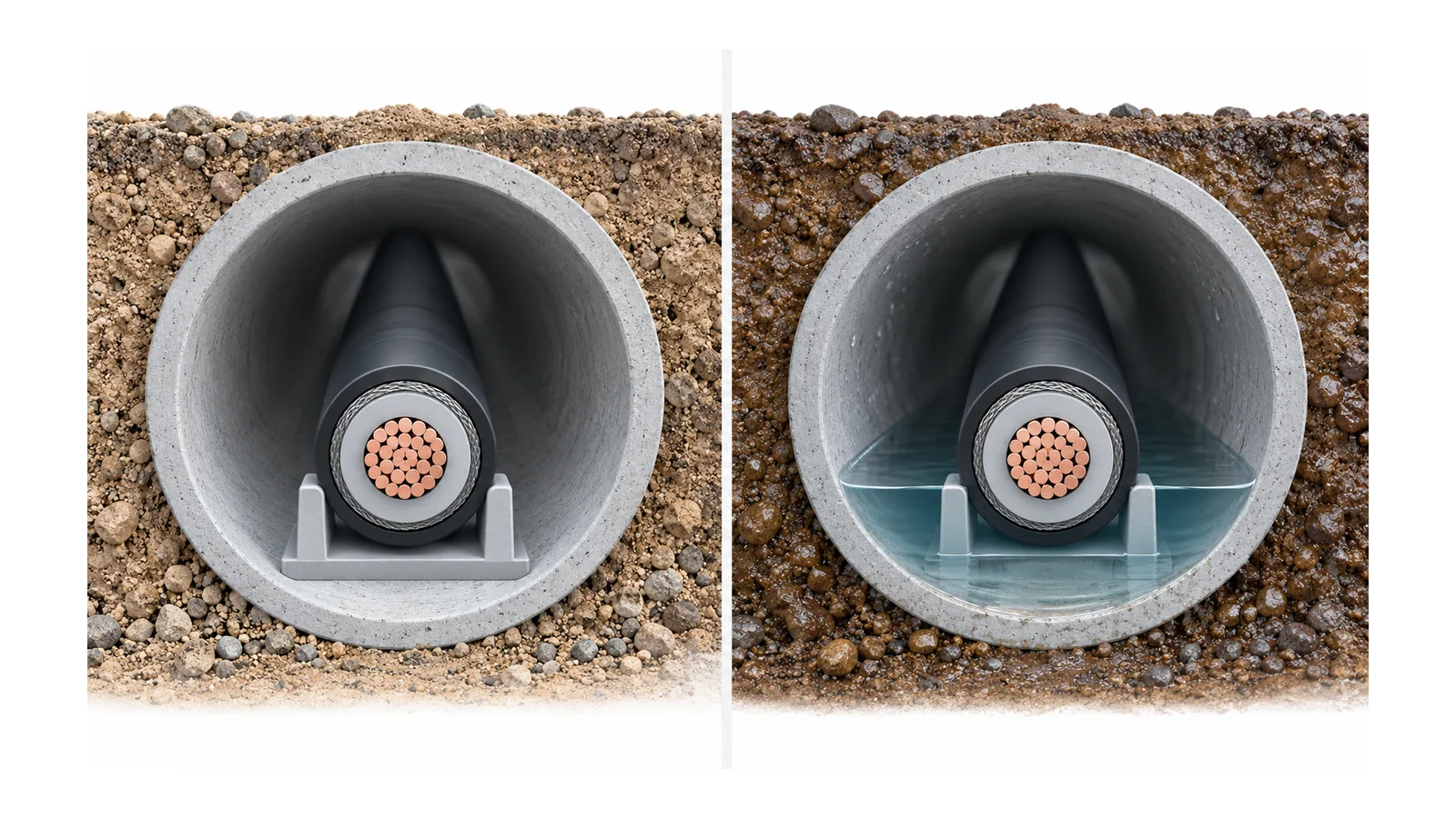
Choose medium-voltage cable insulation by comparing complete cable constructions under the same service conditions. XLPE, tree-retardant XLPE and EPR identify material families; they do not independently establish voltage suitability, wet-service life, ampacity or accessory compatibility. The defensible choice combines voltage-to-earth duty, aging evidence, moisture controls, losses and thermal design, mechanical constraints, and a suitable cable/accessory test basis.
For a wet duct route, insulation aging and water barriers may drive the comparison. For a long dry route, verified dielectric and thermal properties may be more influential. For a constrained installation, cable dimensions, bend limits and accessory interfaces can reject a candidate before material preferences matter. No family is the universal winner.
This guide compares extruded insulation for fixed, shielded alternating-current (AC) MV distribution service. It is not a universal temperature table, a cable-life prediction or a field-test procedure.
Identify the insulation without confusing it with the cable
XLPE is cross-linked polyethylene. TR-XLPE is a tree-retardant XLPE formulation; the designation concerns resistance to water-tree degradation, not a waterproof jacket. EPR is ethylene-propylene rubber insulation, commonly a compounded, filled elastomeric system in this application. Do not treat all formulations, manufacturing generations or screen interfaces within a family as identical.
The University of Connecticut’s cable research overview contrasts filled EPR and XLPE/TR-XLPE systems and discusses water-tree behavior and dielectric loss. It reports comparatively low water-tree susceptibility for the EPR systems it discusses. That is a useful research direction, not proof that every EPR cable is immune to aging or that older XLPE findings describe every modern TR-XLPE construction. The consortium’s research emphasis also warrants care when using its overview as a comparison source.
The insulation lies between the conductor-side screen and the insulation-side screen. Metallic screening, oversheath, any water-blocking layers, conductor construction and accessories remain separate parts of the system. A cable can have the preferred bulk insulation and still be unsuitable because the complete construction does not address the route or connected equipment.
Fix the voltage and standard boundary first
Record nominal system voltage, maximum operating voltage, conductor-to-earth duty, earthing arrangement, expected earth-fault conditions and the installation’s insulation-coordination basis. Compare the candidate’s complete voltage designation and qualification evidence with those inputs. Do not choose insulation thickness from nominal line-to-line voltage alone.
The public scope of IEC 60502-2:2014+AMD1:2024, corrected July 2026 covers construction, dimensions and tests for fixed extruded-insulation cables rated 6–30 kV within its stated scope. It calls attention to radial water ingress and includes longitudinal water-penetration barrier designs and a corresponding test. Special applications such as mining, submarine service and nuclear-containment-related installations are outside that stated scope.
Use the applicable national adoption and project specification. The public catalog establishes scope and the corrected version; it does not establish a particular compound’s temperature limits or prove that a supplied cable passed the required tests. Do not mix an IEC cable designation, a North American insulation-level convention and an unrelated temperature designation as though they describe the same acceptance basis.
Compare the same duty and ask for different evidence
The matrix below is a comparison worksheet. It deliberately avoids assigning one generic temperature, loss factor or lifespan to a polymer family.
| Decision dimension | XLPE | TR-XLPE | EPR | Evidence that resolves the comparison |
|---|---|---|---|---|
| Material identity | Identify the actual compound and manufacturing generation | Verify what tree-retardant designation and qualification apply | Identify the actual rubber compound and applicable formulation | Exact cable construction and material/qualification record |
| Wet electrical aging | Do not assume older and modern XLPE perform identically | Require evidence for the specific wet-aging claim | Low water-tree susceptibility does not remove all aging mechanisms | Relevant aging method, conditions and interpretation for the candidate |
| Dielectric and thermal behavior | Obtain capacitance, loss and thermal inputs | Verify properties of the specific formulation, not standard XLPE by assumption | Obtain compound-specific properties; do not treat research on high-frequency loss as an ampacity result | Values at the relevant voltage, frequency and temperature; complete thermal model |
| Installation mechanics | Use complete-cable dimensions and permitted bend/pull limits | Apply the same route and handling constraints | Do not infer acceptable pulling or bending from the word rubber | Cable-specific limits, route geometry and installation plan |
| Moisture management | Review jacket, radial barrier, longitudinal blocking and terminations | Tree-retardant insulation does not replace those controls | Moisture can still affect interfaces, screens and accessories | Claimed water-control construction and corresponding test evidence |
| Accessories and acceptance | Match screens, insulation diameter and materials | Verify compatibility for the exact cable, not an XLPE label alone | Verify compatibility for the exact cable, not an EPR label alone | Documented cable/accessory combination and installation/test basis |
Apply rejection gates first: voltage or scope mismatch, unmanageable route constraints, unsupported wet-service claims, or incompatible accessories. Compare cost and practical preferences only among candidates that survive those gates.
Separate three water-related questions
Water exposure is not one material property. Treat these questions independently:
- Bulk-insulation aging: how does the specific dielectric behave under the relevant electrical stress and wet-aging conditions?
- Radial ingress: what construction limits moisture entry from outside the cable toward its interior?
- Longitudinal spread: what limits water movement along the cable after a local breach or entry point?
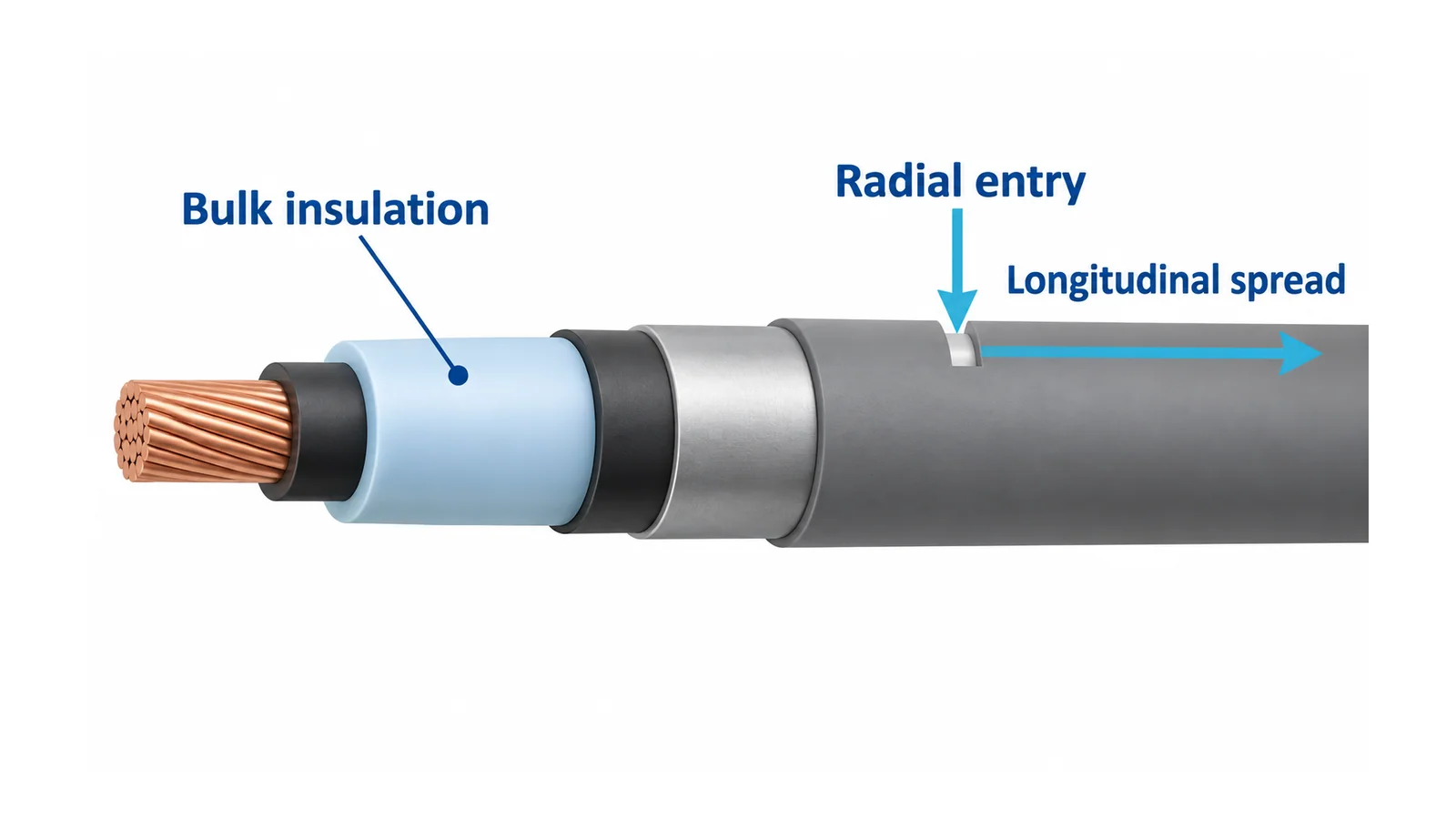
A barrier claim needs an identifiable construction and test basis. Also ask how joints, terminations and damaged oversheath sections preserve the intended protection. A water-blocked length of cable does not make an improperly sealed end acceptable.
Nor does choosing EPR remove the need for aging management. EPRI’s MV cable end-of-life guide discusses EPR aging as well as water-tree degradation in XLPE. Its plant-engineering context should be preserved; it is not a universal replacement interval or a guarantee of a new cable’s life.
Avoid a specification that simply says “waterproof insulation.” Identify which water path is controlled, what the claim covers, and the evidence supporting it.
Recalculate heat and losses for the whole cable
Current-carrying capacity is a system result. Conductor loss, dielectric loss, metallic-screen or sheath loss, thermal resistances, installation arrangement, ambient or soil conditions and adjacent circuits can affect the permitted duty. Keep the candidate’s actual properties in that model.
A family-level statement about dielectric loss does not establish the difference in operating cost for a particular route. Likewise, a cable having a higher permitted conductor-temperature designation does not automatically produce a higher allowable current at equipment terminals. The connected equipment and installation may impose a lower limit.
For a preliminary comparison, hold constant the load, voltage, route, formation, environment and allowable temperatures. Then calculate each candidate using its own dimensions and supported thermal/electrical data. Report the assumptions and unresolved inputs. Do not compare one manufacturer’s laboratory condition with another candidate’s installed rating.
The feeder cable sizing guide explains why load, corrected ampacity, voltage drop and fault checks remain distinct. Its low-voltage (LV) examples are not MV ampacity tables; MV design also needs the appropriate screening, bonding, insulation and accessory treatment.
Preserve accessory compatibility and the test purpose
The insulation choice changes only part of the accessory-selection input. Confirm conductor material and size, insulation diameter, conductor and insulation screens, metallic screening, any water-control layers and the dimensions presented to the accessory. Record the accepted combination before purchasing either item.
Screen removal, preparation and stress-control details belong to the exact accessory procedure. The MV termination guide explains why those interfaces and external creepage can fail independently of the bulk dielectric. Changing cable insulation or construction can trigger a new accessory review even when the system voltage is unchanged.
Specify what each acceptance test is intended to establish, the applicable method, configuration, acceptance basis and competent reviewer. Do not select a field-test voltage or duration from an insulation-family comparison. Different methods answer different questions, and connected accessories or equipment can constrain the test.
In particular, insulation-resistance testing is not a complete measurement of wet-aging resistance, accessory quality or remaining cable life. A high resistance reading cannot fill every evidence gap in the matrix.
Example: a replacement cable in a periodically flooded duct
Assume a hypothetical industrial route with documented MV duty, repeated duct flooding, existing terminations and a planned replacement outage. Three proposed constructions use XLPE, TR-XLPE and EPR. No candidate is selected solely from those names.
The review asks each supplier for the same five evidence groups:
- Complete voltage/construction designation and qualification basis.
- Relevant wet-aging evidence for the proposed insulation, preserving test conditions and formulation identity.
- Radial and longitudinal moisture-control claims and their verification.
- Thermal and installation inputs for the actual duct route.
- Compatible termination/joint combinations and the approved acceptance plan.
If the TR-XLPE candidate has supported aging evidence but no documented longitudinal blocking, record that gap rather than treating “TR” as an answer. If the EPR candidate meets material preferences but does not fit the approved accessory dimensions, resolve that interface before selecting it. If any candidate lacks supported flooded-route suitability, do not manufacture a pass from its standard number.
The result is a conditional selection with documented evidence, not a polymer popularity contest. Release the specification only when the complete cable construction and connected system satisfy the defined duty, route and acceptance basis.