
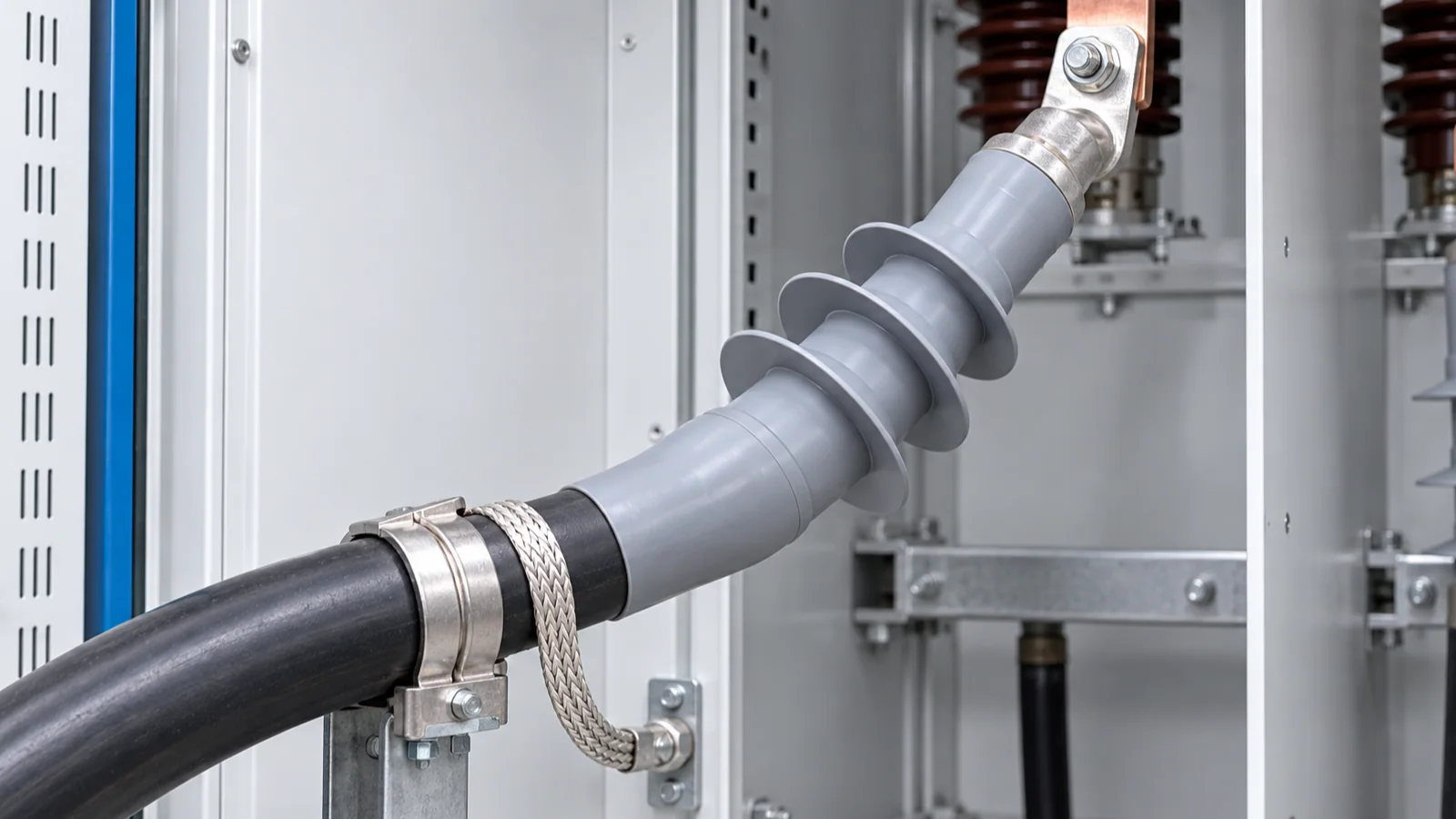
For medium-voltage (MV) cable terminations, the first place to investigate is usually the transition between the shielded cable and the connected equipment—not the bulk cable insulation in isolation. The termination removes or changes the cable screen, reshapes the electric field, exposes an insulating surface to the environment, and carries mechanical and thermal loads at the same time.
A reliable termination therefore has to do four jobs together:
- control the electric-field transition at the screen cutback;
- maintain solid, void-free interfaces between cable and accessory materials;
- provide enough external creepage and clearance for the installation environment; and
- seal, bond, support, and test the assembly according to the applicable voltage class and standard.
Most failure investigations become clearer when those jobs are separated. A damaged stress-control interface, a contaminated shed, a poorly bonded screen, and a system overvoltage may all leave an outage at the same physical component, but they are different failure paths and need different evidence.
Safety boundary
Cable termination inspection, testing, replacement, and failure analysis are tasks for qualified and authorized electrical personnel. The work method must follow the site procedure, the equipment instructions, and the locally adopted electrical-safety rules. In the United States, OSHA 29 CFR 1910.333 requires applicable parts to be de-energized before work unless a defined exception applies, with lockout/tagout and verification of the de-energized condition. Other jurisdictions use different legal frameworks.
This article is an engineering explanation, not permission to work on an energized termination. It does not replace a switching plan, isolation and grounding procedure, risk assessment, test plan, or review by a qualified engineer.
The termination is a field transition, not a cosmetic end
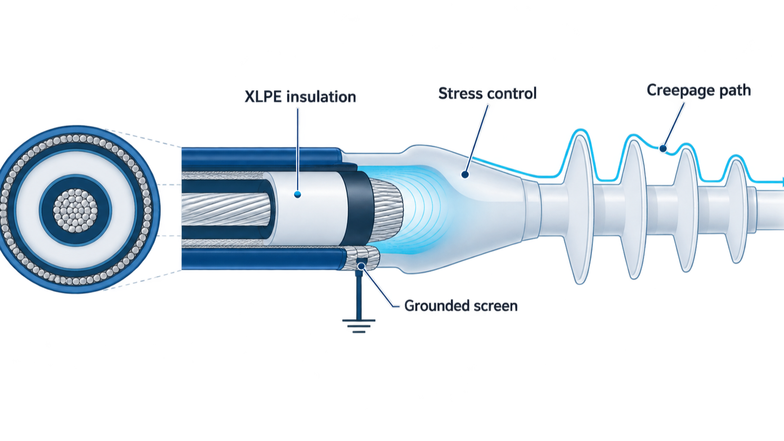
An intact shielded extruded-insulation cable has a broadly controlled radial electric field: the conductor is surrounded by insulation, the insulation screen provides a defined outer boundary, and the metallic screen is connected to the grounding system. At the termination, the insulation screen and metallic screen must end or change form so that the conductor can connect to a lug or bushing. If that transition were made abruptly, the electric field would crowd around the screen edge and any sharp or contaminated feature nearby.
The accessory changes the field distribution with a designed combination of geometry and material properties. A stress cone may use a longer, rounded transition; other designs use capacitive grading, resistive field control, or a combination of methods. The goal is not to make the field disappear. It is to keep the local field and its gradients within the performance envelope of the tested accessory and the connected cable system. CIGRE describes the cable end as a point where the cable’s uniform radial field is distorted and must be controlled by the accessory, with the cable–accessory interfaces becoming critical to system stability. See the CIGRE Technical Brochure 968 summary.
The same accessory also provides external leakage insulation and environmental sealing. An IEEE technical article on shielded power-cable accessories treats stress control, external leakage insulation, and environmental sealing as separate functional requirements, rather than as one generic layer of insulation. That distinction is useful during diagnosis: a termination can have acceptable internal field grading and still fail because water, contamination, or surface tracking defeats the external insulation.
What the accessory has to do
| Function | What it controls | What a failure can look like |
|---|---|---|
| Internal field grading | The change from the screened cable geometry to the conductor connection | Partial discharge, insulation erosion, or breakdown near the screen cutback |
| Cable–accessory interface | Surface roughness, pressure, cleanliness, and material compatibility | Local discharge, tracking, thermal damage, or progressive interface deterioration |
| External leakage insulation | Leakage current over the termination surface when it is wet or contaminated | Dry-band activity, tracking, erosion, or external flashover |
| Environmental sealing | Water, humidity, dust, chemicals, and condensation entering the assembly | Corrosion, surface contamination, swelling, discharge, or loss of insulation performance |
| Screen and earth transition | A defined connection between the cable metallic screen and the grounding/bonding system | Unexpected screen potential, induced voltage, circulating current, or disturbed field conditions |
| Mechanical and thermal support | Cable weight, bending forces, conductor heating, and differential movement | Loss of interface pressure, cracked materials, loose connections, or seal displacement |
No single visual feature proves that all six functions are satisfactory. A termination should be assessed as an assembly matched to a cable construction, voltage class, environment, and installation geometry.
Creepage is not the same as clearance
The two distances are related but they protect against different paths:
- Clearance is the shortest path through air between points at different potential. It is relevant to air breakdown and flashover.
- Creepage is the path along the surface of solid insulation. It becomes especially important when the surface can collect moisture, salt, dust, process residue, or other contamination.
The sheds or skirts on an outdoor termination are not decorative. They lengthen and interrupt the surface path and help manage wetting. But counting sheds or measuring a visible straight-line distance is not a universal creepage calculation. The required insulation coordination depends on the system voltage and withstand levels, pollution and wetting conditions, altitude, material and surface behavior, phase-to-ground and phase-to-phase geometry, and the standard or project specification governing the accessory. IEC 60071-2:2023 provides application guidance for insulation coordination in three-phase AC systems above 1 kV; it is not a substitute for the product-specific accessory requirements or local installation rules.
This is why a termination that looks clean in a dry switchroom can behave differently outdoors, in a coastal location, in a dusty process area, or where condensation forms inside an enclosure. A wet contaminated surface can support leakage current. Local drying and re-wetting can produce dry bands and concentrated surface stress; repeated activity can lead to tracking or erosion. The exact severity depends on the accessory design and environment, so a generic creepage number should not be copied from an unrelated device family.
Why MV cable terminations fail
The table below is a diagnostic map, not a substitute for a site-specific investigation. The “verify” column identifies evidence to collect after safe isolation; it does not prescribe a universal test sequence.
| Failure path | Physical mechanism | Evidence to verify |
|---|---|---|
| Incorrect screen cutback or stress-control placement | The designed field transition is moved, shortened, damaged, or left with an abrupt edge; local stress can increase at the wrong location | Kit and cable identifiers, installation drawings, measured cutbacks, photographs taken during assembly, and the condition of the screen-cutback region |
| Semiconductive residue, nicks, or sharp edges | Conductive residue or a damaged insulation surface creates a local field irregularity; a sharp edge can become a discharge initiation site | Controlled visual inspection, magnified inspection where appropriate, installation records, and qualified electrical test results |
| Voids, gaps, or poor interface pressure | Air or a poorly coupled interface changes the local dielectric conditions; thermal cycling can make the contact state worse | Correct assembly sequence, material compatibility, lubricant or interface treatment specified for the kit, pressure/contact features, and evidence of movement or shrink-back |
| Moisture or contamination ingress | Water, condensation, salts, dust, or chemicals reduce surface insulation performance and can support leakage, tracking, corrosion, or discharge | Seal condition, water paths, enclosure drainage, contamination pattern, corrosion, weather history, and comparison with other phases |
| Insufficient or badly arranged creepage and clearance | The external path or air spacing is not suitable for the actual voltage, pollution, altitude, or equipment layout; surface or air flashover becomes possible | Phase spacing, enclosure geometry, altitude and environment, termination orientation, nearby grounded metal, and the project insulation-coordination basis |
| Screen bonding or grounding problem | A screen or bonding connection is open, loose, incorrectly routed, or inconsistent with the system design; screen potential and field conditions may be disturbed | Bond continuity, connection condition, sheath/screen arrangement, bonding design, induced-voltage history, and any sheath-voltage-limiter or sectionalizing provisions |
| Mechanical or thermal strain | Cable movement, excessive bending, unsupported weight, conductor heating, or differential expansion changes pressure or stresses the seal and insulation | Cable support and bend, lug and connection condition, thermal history, enclosure movement, and compliance with the accessory instructions |
| Wrong accessory or incomplete compatibility | The kit does not match the cable diameter, screen construction, conductor connection, system voltage, environment, or required test basis | Cable construction and dimensions, accessory selection record, component lot, approved combination of materials, and qualification/type-test evidence |
| Switching or lightning overvoltage | A transient or temporary overvoltage adds electrical stress beyond the normal operating condition or exposes a weakness in the termination | Protection and surge-arrester records, switching events, system configuration, insulation-coordination study, and test history |
These paths can combine. For example, a small installation defect may remain stable in a dry indoor environment, then become active after moisture enters the termination or after repeated load cycles reduce interface pressure. Conversely, an external tracking mark may be the final symptom of a deeper sealing, material, or field-control problem.
A failure diagnosis that preserves evidence
The useful outcome of an investigation is not merely a replacement termination. It is a defensible explanation of why the assembly failed and what must change before re-energization.
1. Start with the system and event history
Record the cable type, conductor and screen construction, rated voltage, termination technology, location, phase, load history, switching operations, weather or process conditions, and any recent work. Note whether one phase failed or several, whether the event was immediate after installation or developed over time, and whether identical terminations remain in service.
The timing is evidence. An immediate failure after installation points the investigation toward compatibility, preparation, assembly, connection, or test issues. A later failure can still be installation-related, but it also raises questions about moisture, contamination, thermal cycling, mechanical movement, aging, or system transients. These are diagnostic directions, not proof of cause.
2. Isolate, lock out, and verify before inspection
Treat a cable termination as energized until the authorized procedure proves otherwise. Isolation must account for all sources, backfeed, induced voltage, stored energy, and grounding requirements. For the U.S. OSHA example cited above, a qualified person must use test equipment to verify the de-energized condition and check for induced or unrelated voltage; the test equipment must also be checked around a test above 600 V nominal. Apply the local rule when the work is outside that jurisdiction.
3. Inspect the outside without destroying the evidence
Record the termination before cleaning or disassembly. Look for:
- tracking, erosion, chalking, cracking, puncture, or carbonized paths;
- water marks, salt or dust deposits, insects, chemical residue, and condensation;
- deformed or displaced sheds, damaged seals, loose screens, or corrosion;
- signs of cable movement, side loading, excessive bend, or contact with grounded metal;
- connector heating, discoloration, loose hardware, and damaged support points.
Photographs should include the complete assembly and close views with a scale reference that does not touch the equipment. Do not interpret a clean outer surface as proof that the internal interface is sound.
4. Reconstruct the installation geometry
Compare the installed assembly with the exact accessory instructions and cable data. Check the actual conductor size, insulation diameter, screen type, screen cutback, semiconductive removal, stress-control position, interface preparation, connector, seal, screen bond, and support arrangement. Do not use a generic drawing if the cable construction or accessory family is different.
The installation record matters because a termination is a dimensional assembly. A kit can be electrically appropriate in principle but still fail if the cutback, surface preparation, pressure, or component sequence is wrong. CIGRE’s treatment of interface roughness, pressure, lubricants, physical contaminants, and chemical compatibility is a useful reminder that “the right kit” is not the same thing as “the right installed interface.”
5. Select tests to answer a question
Depending on the system and investigation objective, a qualified team may select screen and sheath continuity checks, insulation-resistance measurements, withstand testing, partial-discharge testing, dielectric-loss measurements, thermal inspection, or laboratory analysis. The correct method, voltage, duration, acceptance criterion, and sequence must come from the applicable standard, asset owner, engineer, and equipment instructions.
A single pass/fail result rarely identifies the root cause by itself. A cable withstand test may show that the assembly survived that test under that condition; it does not automatically establish correct field grading, long-term sealing, mechanical support, or suitability for every operating environment. Record test setup, calibration, weather, temperature, configuration, and limitations.
6. Compare and escalate
Compare the failed phase with the other phases, an identical termination on the same site, and the original installation evidence. If the pattern points to a common preparation or material issue, repairing only the visible failed phase may leave the initiating condition in place. If the failure involves internal damage, material incompatibility, suspected partial discharge, or a non-standard event, preserve the component for qualified forensic or laboratory examination before disposal.
Which standards apply?
The correct standard depends on the cable and accessory, voltage class, jurisdiction, and project specification. The following map is a starting boundary, not a declaration that a product or installation complies.
| Reference | Scope relevant to this article | What it does not prove |
|---|---|---|
| IEC 60502-4:2023 | Type-test requirements for accessories for extruded-insulation power cables from 3.6/6 (7.2) kV through 18/30 (36) kV, within its stated cable and application scope | It does not turn an incorrectly prepared field installation into a tested assembly, and it excludes special applications stated by IEC |
| IEC 61442:2023 | Test methods for accessories for power cables from 3.6/6 (7.2) kV through 18/30 (36) kV | It is a test-method document, not a universal installation instruction or a complete local code |
| IEC 60840:2020 | Test methods and requirements for cable systems, cables, and accessories above 30 kV (Um = 36 kV) up to and including 150 kV (Um = 170 kV) | It is not the default scope for every installation called “MV”; special cable systems may need modified tests or other requirements |
| IEEE 48-2020 | Test procedures and requirements for indoor and outdoor AC terminations on shielded cables, including extruded-insulation cables rated 2.5 kV through 500 kV, except separable insulated connectors | Its broad voltage scope does not replace the project specification, local rules, cable data, or evidence for a particular installed assembly |
| IEC 60071-2:2023 | Application guidance for insulation coordination in three-phase AC systems above 1 kV, including cable-line considerations | It addresses insulation coordination, not human safety or every product-specific accessory requirement |
The edition and national adoption must be checked at project level. Do not mix IEC and IEEE terminology, test sequences, class markings, or acceptance criteria as though they were interchangeable.
A design and installation checklist
Before specifying or installing an MV cable termination, document the following inputs and the verification evidence expected for each one:
- System voltage and insulation level — identify nominal voltage, highest system voltage, phase-to-earth conditions, required withstand levels, frequency, fault duty, and transient environment.
- Cable construction — confirm conductor size and material, insulation type and diameter, conductor screen, insulation screen, metallic screen or sheath, oversheath, and any water-blocking or special construction.
- Accessory compatibility — match the exact cable dimensions and screen construction to the termination technology and component combination. Confirm the selected standard and test basis.
- Environment — define indoor or outdoor service, pollution, wetting, salt, dust, chemicals, UV, condensation, altitude, temperature, and enclosure conditions. Do not use a clean indoor assumption for an outdoor installation.
- Equipment geometry — verify phase spacing, clearance to grounded metal, creepage path, enclosure and bushing arrangement, termination orientation, cable support, bend, and access for inspection.
- Interface preparation — control semiconductive removal, insulation surface condition, cleanliness, approved lubricants or treatments, pressure, component sequence, and protection from contamination during assembly.
- Screen bonding and grounding — document the metallic-screen connection, bonding arrangement, continuity checks, induced-voltage controls, and any sheath-voltage or sectionalizing provisions required by the system design.
- Quality records — retain cable and kit identifiers, installer qualification, environmental conditions, cutback measurements, connection records, photographs, test results, deviations, and review sign-off.
No generic “more sheds” rule, larger termination, or higher apparent insulation rating can compensate for an incompatible cable, a contaminated interface, a missing screen bond, or an installation outside the tested configuration.
Shortcuts that create false confidence
Choosing by voltage alone
Voltage is necessary but not sufficient. Cable diameter, screen construction, conductor connection, insulation level, environment, equipment spacing, and test basis can change the correct accessory.
Treating creepage as a number printed on a drawing
Creepage is an environmental and insulation-coordination question. It must be evaluated with the actual pollution, wetting, material, altitude, and geometry—not copied from a visually similar component.
Assuming a cable test proves the termination
The cable and the accessory form a system, but different tests answer different questions. A passed test does not remove the need to check installation dimensions, surface condition, sealing, bonding, support, and the applicability of the test method.
Cleaning the symptom and re-energizing
Cleaning can remove a visible contaminant; it cannot prove that tracking, erosion, partial discharge, interface damage, or water ingress has stopped. A repair decision should follow the evidence and the asset owner’s acceptance criteria.
Replacing only the failed phase without checking the installation population
If all three phases were prepared with the same method, the failed phase may be the first visible result of a common process or material problem. Check the pattern before declaring an isolated defect.
The practical answer
MV cable terminations fail when one or more transitions are no longer controlled: the internal electric field, the cable–accessory interface, the external creepage and clearance path, the environmental seal, the screen bond, or the mechanical and thermal support. Stress control manages the field at the screen cutback. Creepage manages the surface path outside the termination. Neither function is a substitute for correct cable matching, clean and well-coupled interfaces, sound sealing, suitable spacing, qualified installation, and evidence-based testing.
The most useful specification is therefore not “a termination for this voltage.” It is a complete, traceable assembly definition: cable construction, accessory family, voltage and insulation level, environment, geometry, bonding, installation procedure, qualification basis, and acceptance evidence.
Sources
- CIGRE Technical Brochure 968 — Interaction between cable and accessory materials in HVAC and HVDC applications
- IEEE — Insulation enhancement with heat-shrinkable components. III. Shielded power cable
- IEC 60502-4:2023 — Test requirements on accessories for cables rated 6 kV to 30 kV
- IEC 61442:2023 — Test methods for accessories for power cables
- IEC 60840:2020 — Power cables and accessories above 30 kV to 150 kV
- IEC 60071-2:2023 — Insulation co-ordination application guidelines
- IEEE 48-2020 — AC cable termination test procedures and requirements
- OSHA 29 CFR 1910.333 — Selection and use of electrical work practices