
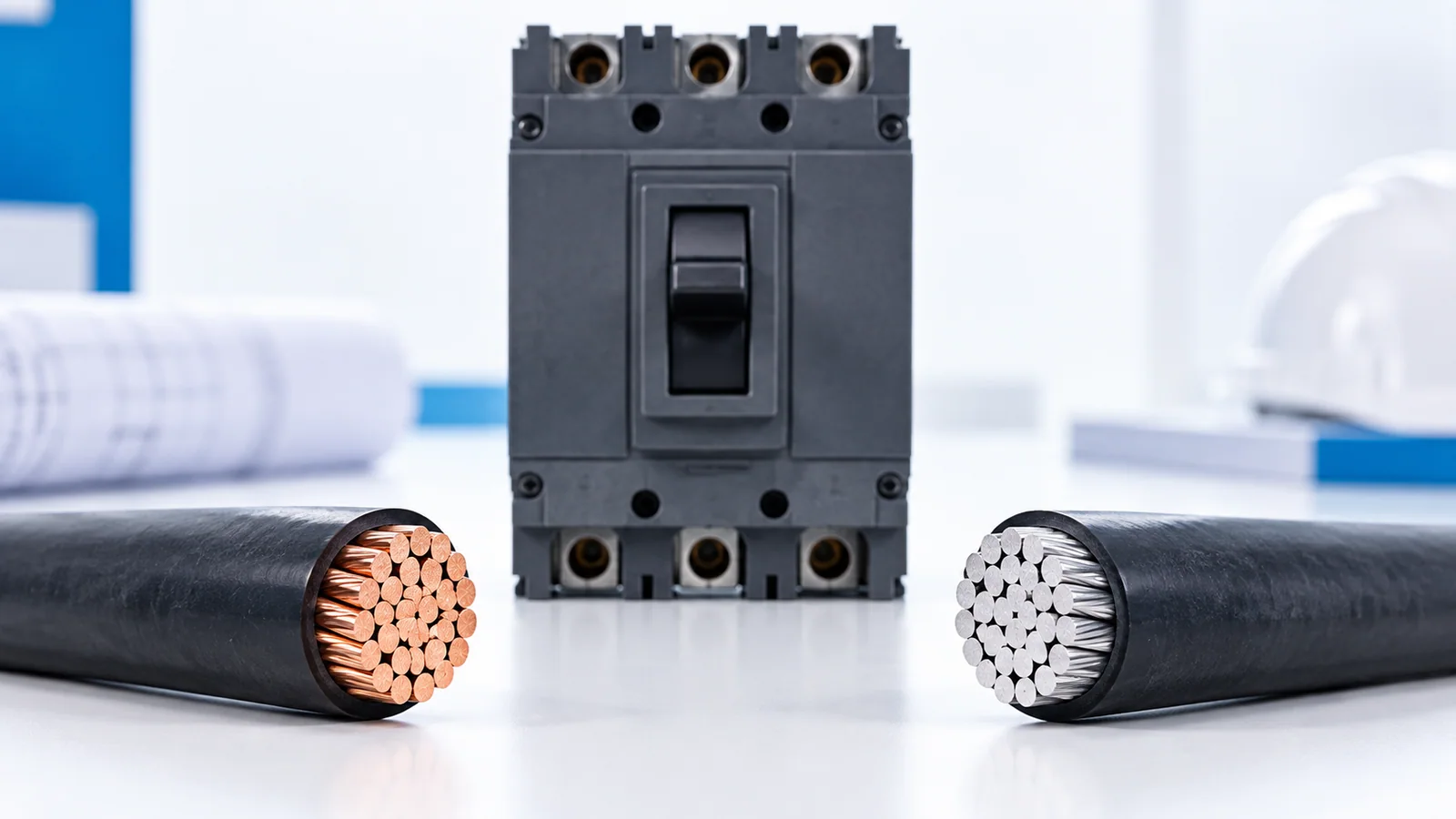
For a U.S. 100-A branch or feeder circuit, a common starting point is 3 AWG copper or 1 AWG aluminum when the equipment terminations permit the 75°C ampacity column, the conductor and installation match the applicable NEC table, and no correction or adjustment reduces usable ampacity below 100 A. If the controlling termination is 60°C, the same table points instead to 1 AWG copper or 1/0 AWG aluminum for a 100-A tabular ampacity. These are not universal installation instructions: a different load, terminal marking, cable method, ambient temperature, conductor grouping or special code rule can change the result.
This article gives a screening calculation for qualified designers and electricians, not a permit or final field approval. Use the NEC edition adopted by the local authority, the actual equipment listing and markings, and the installation method. The NFPA NEC development page identifies the current national code-development context; local adoption can lag it. The table values below are visible in an NFPA-published Table 310.16 committee document. That development document is evidence for the displayed ampacities, not a substitute for the final adopted code text, whose numbering and exceptions must be checked.
Why four plausible answers appear
| Controlling ampacity column | Copper example at 100 A | Aluminum example at 100 A | Essential assumption |
|---|---|---|---|
| 75°C | 3 AWG (100 A) | 1 AWG (100 A) | Both terminations permit 75°C use; table installation conditions hold |
| 60°C | 1 AWG (110 A) | 1/0 AWG (100 A) | A 60°C termination limit controls the final ampacity |
The neighboring smaller sizes fail the corresponding 100-A table test: 4 AWG copper is 85 A in the 75°C column, 2 AWG aluminum is 90 A at 75°C, 2 AWG copper is 95 A at 60°C, and 1 AWG aluminum is 85 A at 60°C. These comparisons use the standard table conditions; they are not a complete code-compliance decision. Special residential service/feeder rules and other exceptions require separate review, so do not apply the table as a universal dwelling-service shortcut.
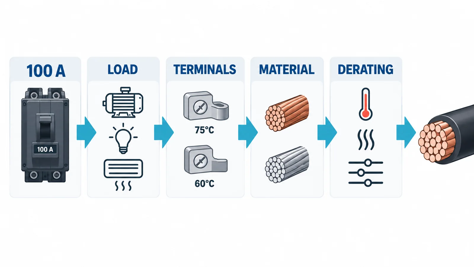
Step 1: establish the load before the conductor
Calculate the branch or feeder load under the adopted NEC rules. Separate continuous and noncontinuous portions. A 100-A breaker does not mean the connected load may draw 100 A continuously in every assembly. Under the common 125% continuous-load sizing framework, a sole 80-A continuous load contributes 100 A to the minimum rating calculation (80 × 1.25 = 100 A). A 100-A continuous load would contribute 125 A and would not fit that ordinary 100-A case. Listed 100%-rated equipment and special rules may change this analysis; confirm the exact listing and code provisions. An NFPA committee report discussing feeder continuous-load sizing illustrates the distinction, but the adopted code is controlling.
Do not use “80%” as a blanket wire-ampacity derating factor. It is a shorthand for a common continuous-load protection calculation. The conductor, terminals and overcurrent device each have their own applicable checks.
Step 2: read both terminal ratings
Check the breaker’s and the load equipment’s terminal markings, accepted conductor material and size range. The lower controlling termination temperature can limit the usable ampacity even if the wire insulation is marked 90°C. A 90°C insulation marking can allow a higher-temperature basis for some correction calculations, but it does not automatically permit terminating at 90°C ampacity. The NFPA committee discussion of termination provisions shows why 100-A-or-less equipment may default to a 60°C basis unless listed and marked otherwise. Confirm the final adopted section and the exact device labeling.
For aluminum, verify that every termination accepts aluminum conductors and that the selected connector, preparation method and torque match its instructions. Do not simply substitute aluminum for copper at the same AWG.
Step 3: apply the installation corrections
The table’s base ampacity is not the final usable ampacity when ambient temperature, more than three current-carrying conductors or another installation condition triggers a correction or adjustment. Apply the adopted code’s method to the actual insulation type and arrangement; then check the terminal limit. For example, if a hypothetical correction/adjustment product were 0.80, a base 100-A figure would yield 80 A before the required terminal-limit analysis. The 0.80 is illustrative, not a factor to use by default. A size that just reaches 100 A in the table may therefore need to increase.
Long runs also need a voltage-drop check; a conductor can meet ampacity yet produce unacceptable voltage at the load. Check fault current, protective-device interrupting rating, grounding conductor, wiring method, physical fit and local requirements. The separate IEC-oriented feeder sizing guide explains general coordination gates but should not be substituted for NEC conductor selection.
Installation boundary and final check
Before any installation or inspection that could expose live parts, qualified personnel must follow the site’s isolation, lockout/tagout and absence-of-voltage verification procedure. OSHA 29 CFR 1910.333 requires qualified-person testing of parts that employees may be exposed to when verifying de-energization. Do not rely on an open breaker handle alone.
A defensible 100-A conductor schedule records: adopted code edition; load calculation and continuous portion; conductor material and insulation; both terminal ratings; base table value; every adjustment/correction; final ampacity; wiring method and length; voltage-drop result; and equipment instructions. Only then is a copper or aluminum AWG answer meaningful.
Sources
- NFPA — National Electrical Code development and edition information
- NFPA public committee document containing Table 310.16 ampacities
- NFPA public committee document on termination temperature provisions
- NFPA public committee report on continuous and noncontinuous feeder loads
- OSHA 29 CFR 1910.333 — electrical work practices